A new process plant for ore processing is currently being planned. The design is only in the first stage. However, three requirements have already been clearly stated: - The bins should have a total capacity of 12,000 m3 bulk material; - The material should have a residence time of 96 hours in the bins; - The system will run continuously. Your colleagues in charge of designing the bins agreed that a total number of 10 bins is required to keep the size of each unit reasonable. The bins will be positioned in 2 rows of 5 as shown in Figure 1. Based on the flow property of the bulk material, mass-flow hoppers have been designed with an outlet dimension of 250 mm width and 1180 mm length. You are now in charge of realizing the conceptual design of a system to control the discharge of the bins. The same discharge system will be installed for each of the 10 bins. The use of screw feeders appears to you as being the best alternative.
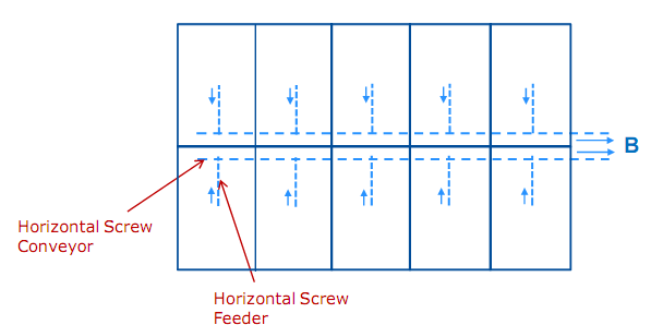
Fig. 1: System configuration as proposed.
After discharge from the hoppers, the material coming from each of the bins should be conveyed away from the bins system up to Point B. For this purpose, you decided to design two horizontal conveyors, each conveyor being able to handle the material coming from each row of 5 bins.
The entire discharge and conveying system will be manufactured of stainless steel.
The results of the flow property testing are as follows:
Flow Property Results:
Bulk density ρb = 2035 kg/m3
Effective angle of internal friction δe = 45°
Friction angle on Stainless Steel Φ = 20°
You are asked to realize the design of the screw feeders and horizontal screw conveyors and produce a report in which you will detail your methodology, assumptions, and results. With your report, you need to show that your proposed design is optimized and the process requirements are fulfilled. You should also detail:
1. Optimal Feeder Geometry
This will require calculation of the volumetric efficiency, throughput, and throughput gradient. A plot of those characteristics in the direction of the feed shall be provided. A comparison of 3 different screw geometries will be performed. This will allow you to select the best geometry. Explain the reason(s) for that choice and draw a schematic of the selected screw geometry including the hopper section and about 1 meter conveying section. All dimensions including clearance and blade thickness should be given.
2. Optimal Rotational Speed for the Feeder
For the 3 screw geometries investigated, calculate the required screw speed. Ensure that the rotational speed required for the screw geometry that you selected is appropriate for a feeder.
3. Design of the Horizontal Screw Conveyors
This will require the selection of screw diameter, shaft diameter and pitch that permit the achievement of the desired throughput. A plot of the throughput achievable according to the screw speed shall be provided for three screw geometries. You will then select the screw geometry that appears to you as being the most appropriate and explain your choice. What is the minimum screw speed required to achieve the desired throughput for the best screw geometry? Indicate this speed on the graph.