Design a 8 to 1 multiplexer using the fourvariable function, Computer Engineering

Assignment Help:

Design a 8 to 1 multiplexer by using the fourvariable function given by
F(A, B, C, D) = ∑ m(0,1,3,4,8,9,15).

Ans. Design of 8 to 1 Multiplexer: It is a four-variable function and thus we require a multiplexer along with three selection lines and 8 inputs. We select to apply variables B, C, and D for the selection lines. It is shown in Table no.1. The first half of given minterms are associated with A' and the second half with A. Through circling the minterms of the function and applying the rules for determine values for the multiplexer inputs, the implementation represented in Table no.2.
The specified function can be implemented along with a 8-to-1 multiplexer as represented in fig.(a). 3 of the variables as B, C and D are applied to the selection lines in order that is B is connected to s2, C to s1 and D to s0.  Hence the inputs of the multiplexer are 0, 1, A and A'. As BCD = 000,001 and 111 output F = 1 because I0 and I8 = 1 for BCD(000), I1 = 1and I9 =1 correspondingly. Thus, minterms m0 = A' B' C' m1 = A' B' C, m8 = A', B', C' and m9 = A' B' C generate a 1 output. While BCD = 010, 101 and 110, output F = 0, as I2, I5 and I6 respectively are equivalent to 0.

Minterm

A           B          C           D

F

0

0            0           0           0

1

1

0            0           0           1

1

2

0            0           1           0

0

3

0            0           1           1

1

4

0            1           0           0

1

5

0            1           0           1

0

6

0            1           1           0

0

7

0            1           1           1

0

8

1            0           0           0

1

9

1            0           0           1

1

10

1            0           1           0

0

11

1            0           1           1

0

12

1            1           0           0

0

13

1            1           0           1

0

14

1            1           1           0

0

15

1            1           1           1

1

Table no.1 Truth Table for 8-1 Multiplexer

613_Design a 8 to 1 multiplexer.png

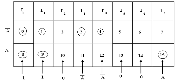
Table no.2 Implementation Table for 8 to 1 MUX

2184_1Design a 8 to 1 multiplexer.png

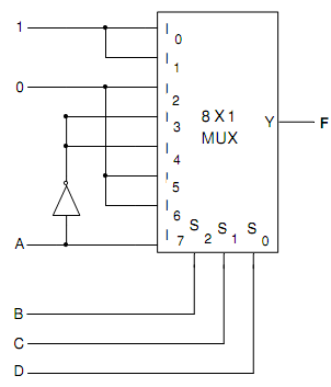
Fig.(a) Logic circuit for 8-to-1 Multiplexer


Related Discussions:- Design a 8 to 1 multiplexer using the fourvariable function

Processing elements (pes) -array processing, Processing elements (PEs)  : E...

Processing elements (PEs)  : Every processing element consists of ALU, local memory and its registers  for storage of distributed data. This PEs has been interconnected via an inte

By which exposing EPROM contents can be erased, EPROM contents can be eras...

EPROM contents can be erased by exposing it to ? Ans. By exposing EPROM contents to Ultraviolet rays, it can be erased. The Ultraviolet (UV) light passes throughout a window i

Hard disk technology - computer architecture, Hard Disk Technology: Fi...

Hard Disk Technology: Figure of a computer hard disk drive           HDDs record data by magnetizing ferromagnetic material directionally, to represent

What is the role of mar and mdr, What is the role of MAR and MDR? The ...

What is the role of MAR and MDR? The MAR (memory address register) is used to hold the address of the location to or from which data are to be transferred and the MDR(memory d

Computer graphics, raster scan and random display technology

raster scan and random display technology

Transaction, Explain Shadow Copy Scheme in detail.

Explain Shadow Copy Scheme in detail.

Database, er table for hospital management system

er table for hospital management system

Find out the access time of ROM using bipolar transistors, The access time ...

The access time of ROM using bipolar transistors is about ? Ans. About 1 µ sec is the access time of ROM using bipolar transistors.

What are the counters, What are the Counters? 1. The Counter is a seque...

What are the Counters? 1. The Counter is a sequential circuit which consists of a set of flip flops connected in a appropriate manner to count the sequence of input pulses.

Design requirements of sequential circuit, What are the Requirements to des...

What are the Requirements to design Sequential circuit Ans . Design Requirements of Sequential circuit: (i) The circuit specifications translated into a state diagram

Write Your Message!

Captcha
Free Assignment Quote

Assured A++ Grade

Get guaranteed satisfaction & time on delivery in every assignment order you paid with us! We ensure premium quality solution document along with free turntin report!

All rights reserved! Copyrights ©2019-2020 ExpertsMind IT Educational Pvt Ltd