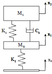
For a vehicle suspension, a basic two-degree-of-freedom "quarter-car" model would be slightly more complicated than the spring-mass-damper system I chose to study in Figure 1. The input would be the road profile xin(t).
A step input would correspond to a sudden bump on the road with a height of 1 meter, which would be unrealistic, but we could simply look at the response to a sudden bump with a height of 10 cm for instance. The responses x1(t) and x2(t) would be proportional to what we would observe for a real step input.
Note that Kt represents the stiffness of the tire while Ks and Cs represent the stiffness and the damping coefficient of the suspension, respectively. Mu is the unsprung mass, and Ms is the sprung mass (where the driver sits).
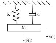
(1a) Derive the equation of motion for the 2nd order mechanical system shown in Figure 1. Show your solutions in function of the damping ration ς and the natural frequency ωn after expressing the damping ratio ς and the natural frequency ωn as a function of M, C and K.
Figure 1: Mechanical system with mass M, damping constant C, and spring constant K. The system input is the displacement F(t). The system output is the displacement x(t).
(1b) The system input is the force F(t) and the system output is the displacement x(t). Derive the transfer function of the system, i.e. X(s) / F(s) as a function of ς and ωn:
(1c) What does a step input mean physically? Now, assume that M = 1 kg. Calculate the extra mass that would needed to be suddenly added to M at t = 0 to yield a response equivalent to a unit step response.
(1d) Derive the solution of the characteristic equation of the system ODE for this system, i.e. find the open-loop poles of this system as a function of ς and ωn. You should have three different solutions based on the value of ς:
Case 1: 0 < ς < 1 (the system is called underdamped)
Case 2: ς = 1 (the system is called critically damped)
Case 3: ς > 1 (the system is called overdamped)
(1e) Assuming M = 1 kg, choose a value for K and a value for C and that they yield an underdamped response. Do not make it too close to a critically damped response (pick 0.1 < ς < 0.4 ). Using Matlab, plot the step response of this underdamped system.
Keep the same values for M (1 kg) and K, and modify the value of C such that it yields a critically damped response. Using Matlab, plot the step response of this critically damped system.
Keep the same values for M (1 kg) and K, and modify the value of C such that it yields an overdamped response. Using Matlab, plot the step response of this overdamped system.
Show the numerical values of your poles for each of the three answers.
(1f) Build a Simulink model of the system and simulate the same three step responses of the system than in question 1.e. Note: Do not use the state-space matrices A, B, C, and D. Build a Simulink model that directly represents the equation of motion (you should have M, C and K in your Simulink diagram).