Define the gauss seidel method, Electrical Engineering

Assignment Help:

Define the Gauss Seidel Method

The Gauss-Seidel method is an iterative method in which the voltage of each node is calculated in turn using the most up to date voltages for the other nodes. The voltage calculated is that which gives the correct solution for the node considered, based upon the data specified and the previously calculated voltages of the other nodes. The method is equally applicable to both a.c. and d.c. circuits.

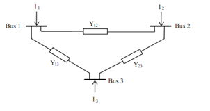
Consider the three busbar system shown in Figure.

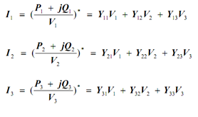
Using Nodal analysis, the current fed into each bus is given as:

 I1  =  Y11 V1 + Y12 V2 + Y13 V3             

 I2  =  Y21 V1 + Y22 V2 + Y23 V3     

 I3  =  Y31 V1 + Y32 V2 + Y33 V3             

or,  in matrix form,

  [I] = [Y] [V]

where Ynn is node n self admittance (sum of all the admittances connected to node n).

 Ynm is the mutual admittance between nodes n and m (sum of the admittances connecting node n to node m)

Note that:  (i) all mutual admittance terms have a negative sign,

  (ii) all injected currents are positive.

1148_Define the Gauss Seidel Method 1.png

Recalling that  S  =  P + j Q  =  V I *

14_Define the Gauss Seidel Method 2.png

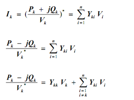
In general, for an n busbar system, the current fed into busbar k is given as:

662_Define the Gauss Seidel Method 3.png

Therefore, the voltage at busbar k is given as:

352_Define the Gauss Seidel Method 4.png

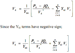
Where Vk and Vi are the voltages at nodes 'k' and 'i', respectively,

  Ykk  is node 'k' self admittance,

Yki   is the mutual admittance between nodes 'k' and 'i',

 Pk - jQk  is the total power flowing into node 'k'.


Related Discussions:- Define the gauss seidel method

Define causal system - discrete time systems, Define Causal System - Discre...

Define Causal System - Discrete Time Systems? A causal system is one which produces an output only when there is an input. All physical systems are causal. In general, a causal

Norton equivalent circuit, Cointruct and simulate using multisim software a...

Cointruct and simulate using multisim software a series voltage regulator to supply 1A to a load at a constant voltage of 9V. The supply voltage to regulator is 15V±10%. The minimu

Current and voltage polarity, why Direct current flow through semiconductor...

why Direct current flow through semiconductors but alternating current cannot flow?

Feedback amplifier, #I want to get lecture notes on Electronic device.and c...

#I want to get lecture notes on Electronic device.and circuits .

Solutions of question bank needed urgent, Need answers of a question bank o...

Need answers of a question bank of power electronics . It is an assignment. Urgent

Microcontroller interfacing, The conveyor system is driven by a 240 Volt 50...

The conveyor system is driven by a 240 Volt 50 Hz AC motor requiring a continuous 1 Amp supply. The conveyor has single direction operation. The loading mechanism for the winder

Define the term assembler directives, Define the term assembler directives....

Define the term assembler directives. An assembler directive is a statement to provide direction to the assembler to perform the function of assembly process. The assembler di

Industrial Automation, 1. Write the Boolean expression and draw the gate lo...

1. Write the Boolean expression and draw the gate logic diagram and typical PLC ladder logic diagram for a control system wherein a fan is to run only when all of the following con

Electrical distribution system, 1. Name the three parts of a programmable l...

1. Name the three parts of a programmable logic controller (PLC) and explain why the PLC is preferred by designers over electromechanical relays. 2. Medium-voltage circuit break

Write Your Message!

Captcha
Free Assignment Quote

Assured A++ Grade

Get guaranteed satisfaction & time on delivery in every assignment order you paid with us! We ensure premium quality solution document along with free turntin report!

All rights reserved! Copyrights ©2019-2020 ExpertsMind IT Educational Pvt Ltd