Centrifugal air compressor, Mechanical Engineering

Assignment Help:

Centrifugal air compressor:

A centrifugal air compressor delivers 15Kg of air per minute. The outlet and inlet conditions are

At inlet: Velocity = 5m/sec, enthalpy = 5KJ/kg

At outlet: Velocity = 7.5m/sec, enthalpy = 173KJ/kg

Heat loss to the cooling water is 756KJ/min find:

(1)  The power of motor required to drive compressor.

(2)  Ratio of inlet pipe diameter to outlet pipe diameter when specific volumes of air at inlet and outlet are 0.5m3/kg and 0.15m3/kg correspondingly. Inlet and outlet lines are at same level.

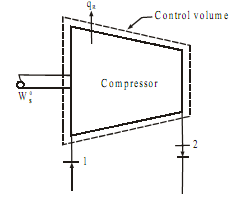
Sol: Device: Centrifugal compressor Mass flow rate mf  = 15Kg/min Condition at inlet:
 

611_Centrifugal air compressor.png

V1  = 5m/sec; h1  = 5KJ/kg

Condition at exit:

V2  = 7.5m/sec; h3  = 173KJ/kg

Heat loss to cooling water Q =  -756 KJ/min

From SFEE

138_Centrifugal air compressor1.png

WS= -3276.23KJ/min = - 54.60KJ/sec                              .......ANS

(negative sign indicate that work done on the system) Thus the power of motor required to drive the compressor is 54.60KW

Mass flow rate at inlet = Mass flow rate at outlet = 15kg/min = 15/60 kg/sec

Mass flow rate at inlet = mf1  = A1.V1/  ν1

15/60 = A1  × 5/0.5

A1  = 0.025m2

Now; Mass flow rate at outlet = mf2  = A2.V22

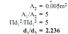
15/60 = A2  × 7.5/0.15

2046_Centrifugal air compressor2.png

Thus the ratio of inlet pipe diameter to outlet pipe diameter is 2.236


Related Discussions:- Centrifugal air compressor

What do you understand by carburization, Q. What do you understand by Carbu...

Q. What do you understand by Carburization? Carburization is initiated by the adsorption of carbon in contact with the surface of the metal and may progress by diffusion along

Mounting systems for the welding head-fixed type:, Fixed type In this se...

Fixed type In this set up, the welding head is kept fixed and the movement required during welding is provided through in the jobs to be welded. A typical application of this arr

Shear and moment diagrams, Shear and Moment Diagrams Determine the anal...

Shear and Moment Diagrams Determine the analytical solution for the maximum stress of the beam shown; compare with stress results from Solid Works. Draw shear and moment diagra

Explain degree of freedom - jig and fixture, Explain Degree of Freedom - Ji...

Explain Degree of Freedom - Jig and Fixture The complete location of components inside a jig or fixtures can be understood with the help of figure. The work piece is a

Breakwater , Let consider the breakwater configuration shown in the figure ...

Let consider the breakwater configuration shown in the figure below. The incident wave conditions at the breakwater are a wave height of 1.5m, wave period of 7.0s and a wave crest

Tensile and compressive force - mechanics, Tensile and Compressive Force: ...

Tensile and Compressive Force: T ensil e Forces A force, that pulls the body, is called as tensile force. Here member AB is tension member carrying tensile force P. As

Scheduling and sequencing, Scheduling and Sequencing: This unit begin ...

Scheduling and Sequencing: This unit begin with the basic concept and the role of scheduling in industry. Several job- sequencing rules to address the manufacturing process ar

Axis of symmetry, Axi s of symmetry If in diagram half part of diagram...

Axi s of symmetry If in diagram half part of diagram is mirror image of next ½ part, then there is a symmetry in diagram. The axis at which symmetry is create, called as axis

Neutral position-shifting of gears , Shifting of Gears: To obtain differen...

Shifting of Gears: To obtain different size combinations of gears, the gears slide on their shafts to mesh with different gears. The position of different gears, e.g. 1st, 2nd, 3r

Write Your Message!

Captcha
Free Assignment Quote

Assured A++ Grade

Get guaranteed satisfaction & time on delivery in every assignment order you paid with us! We ensure premium quality solution document along with free turntin report!

All rights reserved! Copyrights ©2019-2020 ExpertsMind IT Educational Pvt Ltd