Briefly explain single mode and multimode fibres
The optical fibres were categorized within two according to the number of modes it passes as:
• Single mode fibres
• Multi mode fibres
The single mode fibre support just one mode of propagation by the fibre. The single mode therefore supports only one mode that propagates along the axis of the fibre. The diameter of this fibre is little. A single mode fibre is display below:
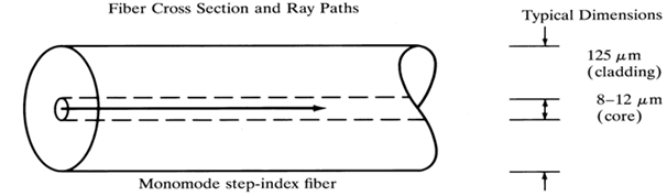
The single mode fibres are intended in long wave length region are the optimum transmission medium, because their attenuation is low and the capacity is high. More over single mode fibre does not have the problem of pulse broadening; because there is no chance of inter symbol interference.
Multi mode fibres hold number of modes. The lowest mode is that one that propagates along the axis. Multi mode fibres were categorized into two as:
• Multi mode step index fibre
• Multi mode graded index fibre
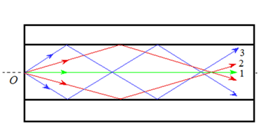
In multimode step index fibre the core have a constant high refractive index and the cladding have a constant refractive index that is lower than the core refractive index. The step index multimode fibre is display below:
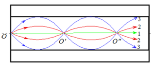
But in graded index fibre the refractive index of the core varies gradually within the core. At the axis the refractive index is high and it decreases towards the cladding, the cladding has a constant refractive index.
The transmission of optical signal by the multimode step index fibre is done through total internal reflection in a zig-zag manner, other than for a graded index multimode fibre it is in a curved path, since the refractive index varies gradually so in which the incoming light undergo number refractions. A graded index multimode fibre is display below:
The disadvantage of the multimode fibre is that it suffers the problem known as intermodal dispersion. When an optical pulse is launched within the fibre, the optical pulse is distributed as number modes within the fibre, each mode travels at slightly various distances. The mode that passes by the axis reach at the destination first and the highest mode that travels more distance reach at the destination at last. Because of this problem in incoming pulse is given as a broadest one at the receiving side. Through the use of graded index fibre this distortion problem in multimode fibre can be decreased.
The diameter of the core of multimode fibre is larger than single mode fibre, so in which the NA of multimode fibre is higher compared to single mode fibre.