Bootstrap, Computer Engineering

Assignment Help:

The device is packaged in a 80 pin PLCC device as shown.The main groupings of the pins are as follows Port A PA0 - PA7 Parallel Port or Timer Port B PB0 - PB7 Parallel Port or High address bus for expansion Port C PC0 - PC7 Parallel Port or Data bus for expansion Port D PD0 - PD5 Parallel Port or Serial communication 

Port E PE0 - PE7 Parallel Port or A/D conversion

Port F PF0 - PF7 Parallel Port or Low address bus for expansion

Port G PG0 - PG7 Parallel Port or Chip enables for expansion

XTAL/EXTAL Connections for crystal (F1N4 Version 4 MHz)

E System Clock output

4XOUT 4 times E clock

IRQ Interrupt request line (Active low)

XIRQ Non Masked interrupt request line (Active low)

MODA/MODB Inputs which set up the mode of operation

VRL/VRH A-D converter reference voltages

R/NW Read/write strobe for external expansion

Reset Bi-direction active low reset line for micro controller

VDD Power supply connection (+5Volts) Vss Power supply connection (0 Volts)

As you can see the design of a micro controller is fairly simple as most of the pins are used for the interfacing to the product. As previously mentioned the 68HC11 has four basic modes of operation, these can be set by hardware or software. The value of the pins MODA/B determines the mode of operation of the controller.

    MODB  MODA    Operation

    1       0    Normal single chip
    1       1    Normal Expanded
    0       0    Special Bootstrap
    0       1    Special Test
 
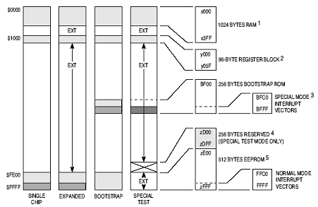
The simplest is the normal single chip mode; this sets the 68HC11 as a self contained micro controller and has no external address or data bus. The 512 byte EEPROM would contain all the program code and is addressed at 0xfe00 - 0xfff. This provides the user with the full range of I/O functions. However because the EEPROM space is 512 byte, programs are usually small approx. 200 lines of program. For larger program space the 68HC11 is expanded with external address and data space, however this uses some of the I/O pins. The memory map for both configurations is shown below
1704_Bootstrap.png


The remaining two modes are special, the first special mode is termed 'Bootstrap', this enables the designer to dynamically load up the controller with its program, instead of blowing the EEPROM externally. This is achieved by  a resident program configuring the serial channel to accept the program code , transfer it into RAM and transfer control to it .This is quite useful for development work when using the single chip normal mode . The remaining mode is the Test mode, this enables the EEPROM and Interrupt vectors to be disabled and mapped externally. This allows the designer full control over the micro controller during development. This is useful if an emulator is not available.


Related Discussions:- Bootstrap

By which finders are connected, In step by step switching line finders are ...

In step by step switching line finders are connected to the (A) Calling subscriber.                   (B) Switching network. (C) Called subscriber.                    (

Two services that are used to deal with communication, Explain about the tw...

Explain about the two services that are used to deal with communication. Message Service: Used by the application servers to change short internal messages, all system commu

Calculate register transfer time, Q. Calculate Register Transfer Time? ...

Q. Calculate Register Transfer Time? A clock isn't included explicitly in any statements discussed above. But it is presumed that all transfers take place during clock edge tra

Determine in brief about laptop computers, Laptop computers Laptop comp...

Laptop computers Laptop computers have the obvious advantage over desk-top computers (PCs) in that they are fully portable. This is of specific value if a user wishes to do wor

Determine the analog output voltage of 6-bit DAC, Determine the analog outp...

Determine the analog output voltage of 6-bit DAC (R-2R ladder network) with Vref as 5V when the digital input is 011100. Ans. The analog output for 6-bit R-2R DAC ladder network

Difference between shadow and override in programming, Overriding tell us o...

Overriding tell us only the methods, but shadowing tells us the entire element.

Difference between latches and flip-flops based designs, What is the differ...

What is the difference between latches and flip-flops based designs Latches are level sensitive whether flip-flops are edge sensitive. So, latch based design and flop based des

Instruction length - assembly language, Instruction Length: Variabl...

Instruction Length: Variable-length instructions (Intel 80x86, VAX) need multi-step fetch and decode, but permit for a much more flexible and compressed instruction set.

Instruction set architecture - assembly language, Instruction Set Architect...

Instruction Set Architecture (ISA): The Instruction Set Architecture (ISA) is the part of the processor which is noticeable to the compiler writer or programmer. The ISA serve

Write Your Message!

Captcha
Free Assignment Quote

Assured A++ Grade

Get guaranteed satisfaction & time on delivery in every assignment order you paid with us! We ensure premium quality solution document along with free turntin report!

All rights reserved! Copyrights ©2019-2020 ExpertsMind IT Educational Pvt Ltd