In order to get your first experience of ARM programming, this way you are familiar with the problem itself, its design, its flow of execution and you can use your own C code as pseudo-code. You are not expected to implement the whole program from assignment
1. The main outline is shown in the ARM file given to you in the file "A2TemplateImage.s". The pseudo code for the overall flow is shown in Figure 1.
Figure 1: Revised Pseudo Code for the ARM program
Initialization:
Open the input file
if problems, print message and exit program
Print a header message to screen
Obtain the input data:
Read row size (Rsize1) and column size (Csize1) of image from the input file
Read exactly (Rsize1)x(Csize1) integers as elements for an image,
convert to characters, and store as 2D char array
Print image as characters with headings to screen
Processing the image:
Construct the Horizontal Mirror of the image into a second image
and print the resulting image with headings to screen
Construct the Vertical Mirror of the image into a second image
and print the resulting image with headings to screen
BONUS: Construct the Diagonal Right of the image into a second image
and print the resulting image with headings (note that this
is the equivalent of constructing the transpose of a matrix)
Closure:
Print a final message to screen
Close the input file
Exit the program
Which data structure should you implement?
You have a choice to implement the 2-dimensional data structure following exactly the C language paradigm, the way a compiler would translate to assembly language code, or to implement it more directly from the assembly language view as a linear array where you use the indices to enforce the 2-dimensional view.
Does it make a difference? It impacts the decision on how you store each element when you read them in.
Obviously it affects also the code you need to develop later for the image transformations and it affects the code to print the 2-dimensional image correctly. In the code given to you, you will find two versions of the routine for printing the image. The first version "PrImage" assumes the allocation, where all elements have been stored consecutively. The second version "PrImage2" assumes the allocation, where elements are stored as a subset of rows and columns of predefined fixed sizes, namely a maximum of 10 rows and 10 columns.
The important goal is that you understand both views and you understand what you are programming. A hint might be that the solution of Figure 6 is probably easier to handle at this point.
Learning about data structures in depth: the 2-dimensional array
It is time to think about the allocation in memory of the 2-dimensional array you are using. It is helpful to view memory as a set of contiguous locations of words/bytes with increasing addresses. Figure 2 shows a snapshot of a section of memory where an array of characters has been allocated as "char Afull[25]".
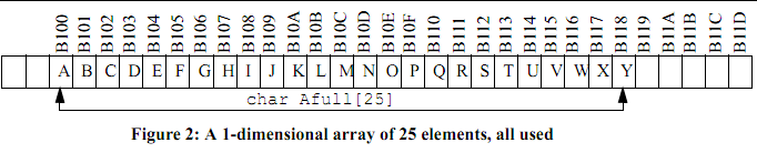
It has been initialized with the letters A through Y as shown. Note that Afull[0] has address 0000B100 and contains "A", while, for example, A full[13] has address B10D and contains "N". In fact the element A full [13] is exactly 13 bytes away in distance from the base address of Afull itself. As a side note, if this had been an array of integers, the element Afull[13]would be exactly 13 x 4 bytes away in distance from the base address of Afull itself, since each elements contains 4 bytes.
Where to start so that you can finish successfully
1. Using the files A2TemplateImage.s and IO_Example_2a.s, make the necessary customization with the goal to have a correct well tested program which can read an image and print it out, together with headings and your name. Choose your memory allocation strategy.
2. Design carefully, using diagrams on paper and pointers, the steps you will need to do the Horizontal Mirror image processing, the easier of the two. Start by using the segment of code to copy a row from a 2D array to another and test it. Then work your way to writing a loop which copies rows (0, 1,..., Nrows-1) of Image to rows (Nrows-1,Nrows-2,...,1,0) respectively of Image2. Look at the solution in C for assignment 1 in A1v2.c.
3. The Vertical Mirror transformation is a little trickier and you should design it and work out all the pointers and position using figures and diagrams before you spend too much time coding and debugging. Make sure you understand how you can use the useful indexed addressing modes:
- [Rn],
- [Rn], #c ,
- [Rn, Rm], etc. Come and ask questions if you do not understand.