Reference no: EM132897247
Unit 19 Electronic Devices and Circuits - Pearson BTEC Level 3 National Foundation Diploma in Engineering
Assignment - Digital electronic devices and circuits
Learning aim: Explore the safe operation and applications of digital logic devices and circuits that form the building blocks of commercial circuits.
You are working as a Junior Technician in a local company that specialises in repairing domestic electronic equipment.
As part of your new role the owner has been providing you with opportunities to develop your skills and knowledge of electronic devices and circuits.
They would now like you demonstrate that you can use a range of test equipment and software to investigate commonly used digital electronic devices and the type of circuits in which they are used. They have asked you keep accurate records of everything you do so that you can refer to them later as you build up your skills and knowledge base.
Task 1 You have been asked to carry out a range of theoretical and practical investigations and evaluations into digital devices and circuits.
To do this:
Your tutor will provide you with information about two types of circuit that you need to investigate:
(a) One combinational logic circuit; and
(b) Two sequential logic circuits
You will also need to provide evidence that you have consistently worked safely in accordance with relevant risk assessments.
You need to produce a report that includes information about the operation of a range of circuits, including comparisons between theoretical values, simulated values, and those measured practically. You will investigate the following:
a) a combinational logic circuit;
b) a 3-bit shift register circuit; and
c) a 3-bit asynchronous (ripple) counter circuit.
To do this you will need to work systematically, following the guide below:
Combinational logic circuit
A chemical process is controlled by a logic circuit. The circuit uses three sensors A, B and C, which switch an alarm,
Q = 1, when certain conditions are reached.
|
Inputs
|
Description
|
Binary
|
|
A
|
Flow rate ≥ 5 litre/second
|
1
|
|
Flow rate < 5 litre/second
|
0
|
|
B
|
Temperature ≥ 30oC
|
1
|
|
Temperature < 30oC
|
0
|
|
C
|
Pressure ≥ 1 atmosphere
|
1
|
|
Pressure < 1 atmosphere
|
0
|
You should:
• Draw the truth table for the logic circuit if the conditions for the alarm Q=1 are:
Flow rate < 5 litre/second and Temperature ≥ 30oC
Or
Flow rate ≥ 5 litre/second and Temperature ≥ 30oC and Pressure < 1 atmosphere
• Use this information to write a Boolean expression for the truth table using AND, OR and NOT gates.
You then need to:
(i) Construct a schematic diagram and simulate the operation of the logic circuit using standard logic gates.
(ii) Minimise the logic circuit using a Karnaugh Map, and then construct a schematic diagram, and simulate the operation of the minimised logic circuit, using standard logic gates.
(iii) Use De Morgan's Theorems to convert the minimized circuit to use only NAND gates.
(iv) Build a prototype of your final circuit and verify that it meets the conditions in the truth table, and then compare the results from theory, simulation and measurement.
3-bit shift register
You should:
• Identify the pin out of a 74HC74 dual D-type flip-flop with positive edge trigger [or specify an equivalent that you have available]
• Construct the schematic circuit of a 3-bit shift register using D-type flip-flops in your ECAD package. The 74HC74 in the schematic has Set and Reset pins held high (logic 1) to allow changes at the D pin to clock through to the output Q. [or give equivalent detail for D-type available.]
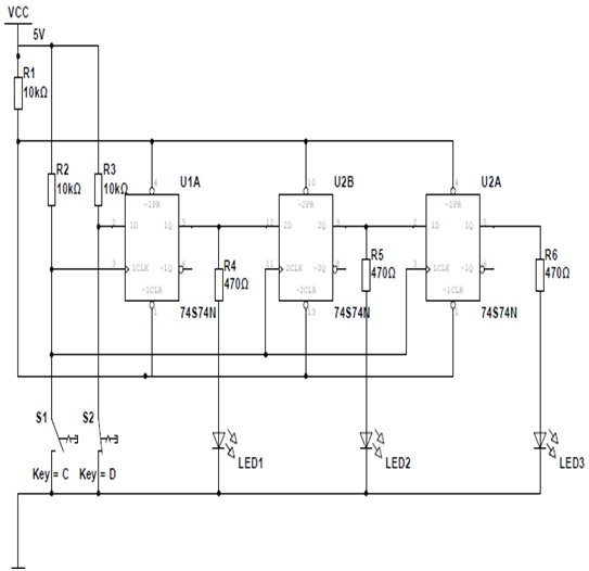
(i) Use the schematic to simulate the behavior of the circuit by setting data values at the D1 input and clocking them through.
(ii) Build a prototype of the circuit and demonstrate that it works as expected, and then compare the results from theory, simulation and measurements
(iii) What practical improvements would you make to the circuit?
(iv) The circuit above shifts data from left to right. Draw a schematic diagram to show how logic gates can be used to enable the data to be shifted from right to left.
(v) Simulate the circuit designed in (iv) to demonstrate how the circuit can shift data from left to right or right to left.
3-bit asynchronous (ripple) counter
You should:
• Identify the pin out of a 4027B dual JK flip-flop with positive edge trigger [or specify an equivalent that you have available]
• Construct the schematic circuit of a 3-bit asynchronous counter using JK flip-flops in your ECAD package. The 4027B in the schematic has Set and Reset pins held low (logic 0) to allow changes to clock through to the output Q. [or give equivalent detail for JK available.]
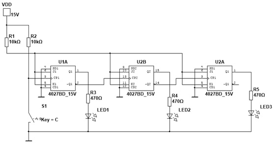
(i) Use the schematic to simulate the behavior of the circuit by using S1 as a manual clock.
(ii) Build a prototype circuit and verify that it works as expected, and then compare the results from theory, simulation and measurements.
(iii) What practical improvements would you make to the circuit?
(iv) Draw a schematic diagram to show how logic gates can be added to the up-counter in the diagram to convert it into an up/down counter.
(v) Simulate the circuit designed in (iv) to demonstrate how the circuit can be used as an up or down counter.
Attachment:- Digital electronic devices and circuits.rar