Reference no: EM131081275
Instructions:
Please download this document and type in your answers for questions in parts 1, 2, and 3; save this document using the following format: CE212Lab1Bfirstname_lastname.doc.
Introduction
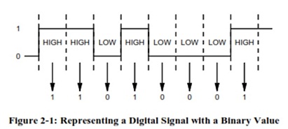
Signals in binary digital systems have only two valid states - LOW and HIGH. Because of this, the binary
number system is a convenient way to represent digital data. Just as the decimal number system uses ten digits (0 through 9) to represent decimal values, the binary number system uses two digits (0 and 1) to represent binary values. These bi nary digits, or bits, can represent the LOW and HIGH states of digital data. Figure 2-1 shows how a binary value can represent the states of a digital signal.
A problem with binary numbers is that people are not very good at working with long strings of zeroes and ones. Engineers, technicians, and programmers who work with computers and other digital devices must be able to convert binary values to a more familiar or convenient number system. In this experiment you will convert binary values to decimal, octal, and hexadecimal, and use Multisim circuits to verify that you have converted the numbers correctly. You will also compare the basic operation of combinational and sequential logic circuits.
The Multisim circuits for this experiment are provided so that you can observe and compare the operation of combinational and sequential logic circuits. At this point you do not need to know how they work. Note that the circuit in Part 1 will run very slowly, as it is more complex than the circuits in Parts 2 and 3 that you will use.
Reading
Kleitz, Digital Electronics: A Practical Approach with VHDL, 9th Edition, Chapter 1.
Multisim Circuits
Part 1: Digital_Exp_02_Part_01
Part 2: Digital_Exp_02_Part_02
Part 3: Digital_Exp_02_Part_03
Lab Objectives
Part 1: Apply the weighted-column method to convert binary values to corresponding decimal values and verify your answers with a sequential binary-to-decimal conversion circuit.
Part 2: Apply the group-by-three method to convert binary values to corresponding octal values and verify your answers with a combinational binary-to-octal conversion circuit.
Part 3: Apply the group-by-four method to convert binary value to corresponding hexadecimal values and verify your answers with a combinational binary-to-hexadecimal conversion circuit.
Part 1: Binary-to-Decimal Conversion
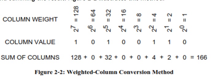
A standard conversion technique for converting a binary value to a decimal value is the weighted-column method. This method multiplies the bit value for each column by the binary weight of that column and summing the result. Figure 2-2 illustrates this method.
Another technique, used in simple computer programs, is to count down in binary to 0 while simultaneously counting up from 0 in decimal. When the binary count equals 0, the decimal value equals the original binary value.
In this part of the experiment you will use the weighted-column method to convert binary values to decimal and verify your answers with a Multisim circuit that uses the simultaneous counting method.
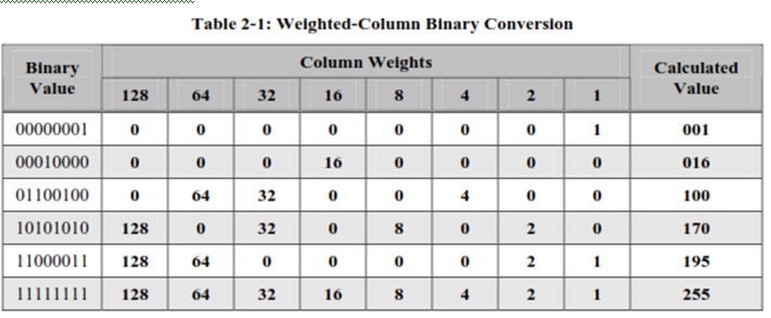
1) For each of the binary values in Table 2-1, enter the weighted-column value for the bit that
Corresponds to that column.
- If the bit that corresponds to a column is "0", enter "0".
- If the bit that corresponds to a column is "1", enter the indicated weight for that column.
2) For each binary value in Table 2-1, sum the column weight values and enter the sum in the "Calculate
Value" column for that row.
3) Open the file Digital_Exp_02_Part_01.
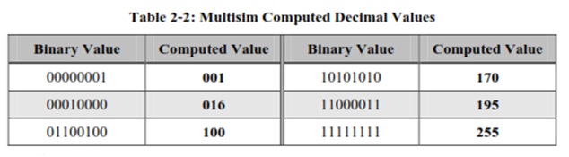
4) Set the DIP switch J to the first binary value in Table 2-2.
- Click on a switch to slide the white portion down for a "0".
- Click on a switch to slide the white portion up for a "1".
5) Start the simulation.
6) Press the "L" key to close switch J. This will clear the decimal display and load the binary value into
the binary counter.
7) Verify that the probes X1 through X2.
match the binary value. A lit probe indicates a "1", and an unlit probe indicates a "0".
8) Press the "L" key to open switch J2. This will begin the conversion and light up probe X
to indicate that the conversion is in progress. The decimal value will change as the counters sequence through the count.
9) When probe X9 goes off, indicating that the conversion is complete, stop the simulation.
10) Copy the value in the digital display into the "Computed Value" column of Table 2-2.
11) Repeat steps 4 through 10 for the remaining binary values in Table 2-2.
Questions for Part 1
1) How does the simulation time (time for the circuit to compute the decimal value) change as the binary values get larger? Why?
2) Set the DIP switch J1 to 11111111, start the conversion process, and watch the simulation time at the lower right-hand corner of the Multisim screen. How does the simulation time (the time the circuit experiences) compare to real time (the time you experience)?
Part 2: Binary-to-Octal Conversion
Converting binary values to values in binary-based number systems such as Base 8 (octal) and Base 16
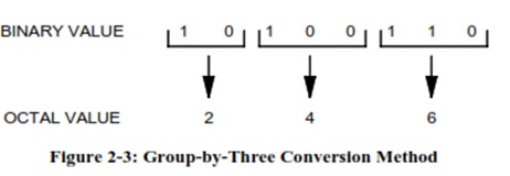
(hexadecimal) is much simpler than converting binary values to non-related number systems such as Base 10(decimal). Because eight is the third power of two, converting a binary value to octal consists simply of grouping bits by three, beginning from the right, and then converting the groups to octal digits. Figure 2-3 illustrates this method. Note that the leftmost group may, as in this case, contain less than three bits. When this happens, assume the missing bits in the group are zeros.
In this part, you will use the group-by-three method to convert binary values to octal and use a combinational Multisim circuit that groups bits to verify your answer. Table 2-3 shows the 3-bit groups that correspond to each octal digit.
1) For the first binary value in Table 2-4, write the bit groups in the corresponding "Bit Group" column of
Table 2-4. Be sure to start from the right when grouping by three!
2) Use Table 2-3 to record the octal value of each bit group in the corresponding "Octal Value" column of Table 2-4.
3) Repeat steps 1 and 2 for the remaining binary values in Table 2-4.
4) Open the file Digital_Exp_02_Part_02.
5) Start the simulation.
6) Set the DIP switch J1 to the first binary value in Table 2-5.
- Click on a switch to slide the white portion down for a "0".
- Click on a switch to slide the white portion up for a "1".
7) Verify that the probes X1 through X8 match the binary value. A lit probe indicates a "1", and an unlit
probe indicates a "0".
8) Copy the value in the digital display into the "Computed Value" column of Table 2-5.
9) Repeat steps 6 through 8 for the remaining binary values in Table 2-5.
10) Stop the simulation.
Table 2-5: Multisim Computed Octal Values
|
Binary
Value
|
Computed
Value
|
Binary
Value
|
Computed
Value
|
Binary
Value
|
Computed
Value
|
|
00000011
|
|
01010101
|
|
10100110
|
|
|
00001110
|
|
10000001
|
|
11111111
|
|
Questions for Part 2
1) How does the simulation time (time for the circuit to compute the decimal value) change as the binary values get larger?
2) Compare the display circuitry for Digital_Exp_02_Part_01 and Digital_Exp_02_Part_02. Note that the
binary-to-octal conversion circuit uses the same display circuitry as the binary-to-decimal conversion
circuit. Why is this possible?
Part 3: Binary-to-Hexadecimal Conversion
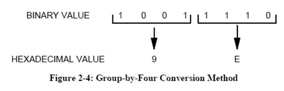
Binary-to-hexadecimal conversion is similar to binary-to-octal conversion, except for the number of bits in each group. Because sixteen is the fourth power of two, converting a binary value to hexadecimal consists of grouping bits by four, beginning from the right, and converting each group to a hexadecimal digit. Figure 2-4 illustrates this method. If the leftmost group contains fewer than four bits, assume the missing bits are all zeros.
Hexadecimal (or "hex") is a popular number format in computing, as computers work with binary values that are multiples of four bits. In this part, you will use the group-by-four method to convert binary values to hexadecimal and use a combinational Multisim circuit that groups bits to verify your answer. Table 2-6 shows the 4-bit groups that correspond to each hexadecimal digit.
1) For the first binary value in Table 2-7, write the bit groups in the corresponding "Bit Group" column of
Table 2-7. Be sure to start from the right when grouping by four!
2) Use Table 2-6 to record the hexadecimal value of each bit group in the corresponding "Hexadecimal
Value" column of Table 2-7.
Table 2-6: Hexadecimal Digits for 4-Bit Binary Groups
|
Bit Group
|
0000
|
0001
|
0010
|
0011
|
0100
|
0101
|
0110
|
0111
|
|
HexadecimalDigit
|
|
|
|
|
|
|
|
|
|
Bit Group
|
1000
|
1001
|
1010
|
1011
|
1100
|
1101
|
1110
|
1111
|
|
Hexadecimal Digit
|
|
|
|
|
|
|
|
|
3) Repeat steps 1 and 2 for the remaining binary values in Table 2-7.
Table 2-7: Group-by-Four Conversion Method
|
Binary
Value
|
Bit Group
|
Hexadecimal Value
|
|
Left
|
Right
|
Digit 1
|
Digit 2
|
|
00010001
|
|
|
|
|
|
01111110
|
|
|
|
|
|
10101111
|
|
|
|
|
|
11000010
|
|
|
|
|
|
11100101
|
|
|
|
|
|
11111111
|
|
|
|
|
4) Open the Multisim file Digital_Exp_02_Part_03.
5) Start the simulation.
6) Set the DIP switch J1 to the first binary value in Table 2-8.
- Click on a switch to slide the white portion down for a "0".
- Click on a switch to slide the white portion up for a "1".
7) Verify that the probes X1 through X8 match the binary value. A lit probe indicates a "1", and an unlit
probe indicates a "0".
8) Copy the value in the digital display into the "Computed Value" column of Table 2-8.
9) Repeat steps 6 through 8 for the remaining binary values in Table 2-8.
10) Stop the simulation.
Table 2-8: Multisim Computed Hexadecimal Values
|
Binary Value
|
Computed Value
|
Binary Value
|
Computed Value
|
|
00010001
|
|
11000010
|
|
|
01111110
|
|
11100101
|
|
|
10101111
|
|
11111111
|
|
Questions for Part 3
1) What are some advantages of converting values from binary format to hexadecimal format compared toconverting values from binary format values to octal format?
2) Why does the binary-to-hexadecimal converter circuit use different display circuitry than the binary-to decimaldisplay circuit?