Reference no: EM133516098
Reinforced Concrete Design Project Assignment
Design Tasks:
The general layout of a reinforced concrete floor of a five-storey office building is shown in Figure 1. Each storey height is 3.8 m. The slab thickness is 180 mm, beams are 400 mm × 600 mm and the columns are 400 mm × 400 mm. You are required to design a typical beam on either Grid 1 or 4.
All reinforcements are to be detailed. Sketch plans, elevations and cross sections to demonstrate the type, location and amount of reinforcing steel to be used for the beam (top, bottom, shear).
The task does not require you to calculate any external dimensions of beams. The architect has set the dimensions of the concrete profile and you are constrained with them. All beam widths and depths have been provided in Figure 1. As a part of the design, you are required to check the adequacy of these dimensions, and document the reinforcement required, in accordance with AS3600-2018.
The following grades of reinforcement and bar sizes are to be adopted in your design:
Beams: Flexural N20
Shear & crack control N10
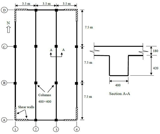
Figure 1. Typical Floor Layout (Not to Scale)
Design Criteria
The following criteria must be adhered to:
(a) The characteristics compressive strength of concrete f'c = 32 MPa.
(b) All reinforcing steel to be class N with 500 MPa yield strength.
(c) The maximum nominal aggregate size is 20 mm.
(d) All reinforced concrete to be designed for a fire resistance period of 120 minutes.
(e) The office is located in Perth, CBD.
(f) The beam is to be design for a deflection limit of 1/250 (Table 2.3.2 AS3600). NO need to check for incremental deflection. The following loads are to be adopted in your design:
Office Floor:
(i) Permanent action (ceiling services, floor finish, partitions) (not self weight) 1 kPa
(ii) Imposed action (Use AS/NZS1170.1) ? kPa
Important Notes
- All the lateral loads from wind and earthquakes are to be resisted by the corner shear walls.
- You are not required to design for lateral loads due to wind and earthquakes.
- Start your design by determining the required cover for durability and fire in order to get the effective depths for the beam.
- In order to estimate the design actions, use appropriate load combinations listed in AS/ NZS1170 and in AS3600.
- Use the deemed to comply methods for checking the beam deflections.
- Use the simplified analysis method in AS3600 to determine the design bending moments and shear forces for the beam.
- All supports for beams should be assumed as being fully fixed.
- Ensure bar spacing and general detailing of reinforcement in accordance with AS3600 are followed.
- You need to check the beam deflections based on the given dimensions and determine if the given depths are sufficient or not. Even if they are not sufficient, you are still required to do the design using the given dimensions. There is NO need to increase the depth for the design.
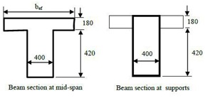
- Note the beam section at mid-span is a T section rather than rectangular section with part of the slab acting as the flange.
- Note the beam section close to the supports is rectangular with the tensile reinforcement at the top of the section.
- For a T section
bef = bw + 0.2a (Cl 8.8.2)
a = for continuous beams may be taken as 0.7L
Report Format:
The first page of your design must be marked A and is a title page, containing the the names of group members and, an indication of each member's involvement in specific activities. The second page marked B is the index of the succeeding pages of computations and sketches. The following pages should be numbered consecutively, the number including the total number of pages. For example 4/21 or 4 of 21.
The following sequence of paragraph headings is suggested.