Pulse width modulator

Assignment Help Electrical Engineering
Reference no: EM13712

PULSE WIDTH MODULATOR

Part-1

Introduction:

A pulse width modulation (PWM) circuit works by varying the duty cycle of the square wave while keeping the period fixed. In simple terms, it is a technique to provide a logic "1", and a logic "0" for a controlled period of time.

DUTY CYCLE : The duty cycle is the percentage of the period of a square wave that that signal is high. A 50% duty cycle would be high for 50% of the time and low for 50% of the time. Likewise, a 10% duty cycle would be high for 10% and low for 90%.

2178_Pulse width modulator.png

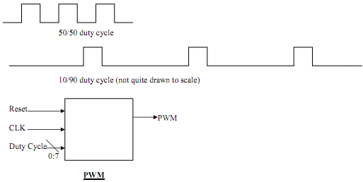
A block diagram for the system is shown above.

Implementation:

A simple VHDL description of the circuit might look like this:

CONSTANT duty_cycle : INTEGER := A; -- for easy change of duty cycle

Signal count_value      : Integer Range 0 to max_value;

Signal PWM                 : STD_LOGIC;

PROCESS(CLK)
BEGIN
IF RISING_EDGE(CLK) THEN
IF (count_value < max_value) THEN
count_value <= count_value + 1;           -- note that we use a counter to keep track
IF (count_value = A) THEN                      -- of the fraction of the cycle for which PWM is High

PWM <= NOT(PWM);                               -- toggle PWM Bit
END IF;
ELSE
count_value <= 0;
PWM <= '1';                                             -- assuming you want to
start with '1' level
END IF;
END IF;
END PROCESS;

This is just one way of implementing the Pulse Width Modulator.

However, for your lab assignment, implement your circuit according to the flow chart given below.

1924_Pulse width modulator2.png

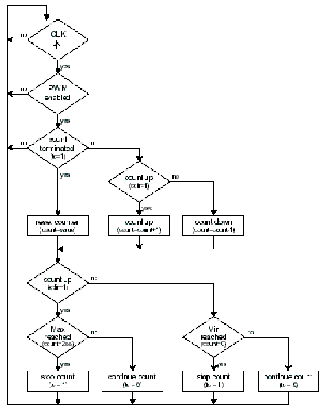
Write and test the VHDL code that represents a description of this PWM circuit using Quartus II.

Hand in your code and a fully documented simulation, being sure to completely describe your design and test methodology.

Part 2:

Use the clock division code that you designed for the traffic light controller in the first lab and for programming the Altera DE-II board. You should be able to demonstrate the change in the turn on times for the LEDs. Use the toggle switches for changing the duty cycle and LEDs as the respective outputs. Prepare an excel sheet for the relevant error compared to the required duty cycle.

Reference no: EM13712

Questions Cloud

Design a course registration system : Create an application which represents a simplified course registration system using ArrayLists and HashMaps.
Effect of financial leverage : The Effect of Financial Leverage and working capital management
The role of hr : The role of HR in the 21 st  century is becoming increasingly vital. A significant claim in support of Strategic Human Resource Management is with regards to its contribution to the firm's competitive advantage
Design a program that assigns seats on an airplane : Write a program that allows an instructor to keep a grade book and also design and implement a program that assigns seats on an airplane.
Pulse width modulator : A pulse width modulation (PWM) circuit works by varying the duty cycle of the square wave while keeping the period fixed.
Design a base class shape with virtual functions : Design a base class shape with virtual functions
Develop a dynamic website open university : Develop a dynamic website Open University
Traffic light controller : The schematic of the traffic light controller
Writing a class : Build a class for a type called Fraction

Reviews

Write a Review

Electrical Engineering Questions & Answers

  Paper on orthogonal frequency-division multiplexing

This document is shown a paper on Orthogonal frequency-division multiplexing with advantages, disadvantages and uses.

  Impact of electron energy

Briefly discuss the impact of electron energy, electron current and target on the Bremsstrahlung generated.

  Explain scada system

Explain the function of the HMI in a SCADA system.

  Lithium ion battery technology

The paper includes Lithium ion battery technology with its advantages and disadvantages. The paper discusses about the Lithium air battery in which detailed reactions of Lithium with air including nonaqueous as well as aqueous are given.

  Resultant waveform of the odd harmonic series

Prepare an Excel graph showing the individual components and summated resultant waveform of the odd harmonic series resulting in an approximate square wave.

  Traffic light controller

The schematic of the traffic light controller

  Model a discrete-time system

To understand di erent signal models To be able to model a discrete-time system and design simple signal processing algorithms.

  Draw a relay construction diagram

Draw a relay construction diagram and briefly explain the operation of a relay.

  Design a 2-digit 24 second shot-clock

Design a 2-digit 24 second "shot-clock" countdown timer with pushbutton controller.

  Power transformers and tariffs

Construction of different types of power transformer, significant energy savings

  Function of the hmi in a scada system

This assignment contains electronics engineering questions like State the commonly found components of a SCADA (Supervisory control and data acquisition) system. and decribe the function of the HMI in a SCADA system.

  Frequency division multiplexing

Write a short technical report on Frequency Division Multiplexing

Free Assignment Quote

Assured A++ Grade

Get guaranteed satisfaction & time on delivery in every assignment order you paid with us! We ensure premium quality solution document along with free turntin report!

All rights reserved! Copyrights ©2019-2020 ExpertsMind IT Educational Pvt Ltd