Reference no: EM132321218
Assignment Brief and Guidance -
Learning Outcomes -
- Apply concepts of physics to develop solutions to hydrostatic and hydrodynamic problems.
- Calculate forces related to fluids at rest and in motion.
- Develop practical solutions for the distribution of fluids within correctly sized pipes.
- Calculate the hydrostatic pressure exerted on substructures for a given context.
- Design complex columns and piled foundations based on calculation.
Part A -
Q1. As an assistant engineer, in order the calculate the friction loss of a fluid flow, you are being asked analysis the fluid conditions of the fluid flow. The following data of the fluid flow has already been measured:
There is a fluid flow between two parallel plates 80mm apart. The velocities of the flow were found by direct measurement as the table below:
|
Distance from one plate (mm)
|
0
|
10
|
20
|
30
|
40
|
50
|
60
|
70
|
80
|
|
Velocity (m/s)
|
0
|
23
|
28
|
30
|
32
|
29
|
22
|
15
|
0
|
a. Plot the velocity distribution curve and determine the mean velocity of the flow and comment the flow condition and characteristics of the flow.
b. If the fluid flow is a turbulent flow, use a diagram or model to illustrate the flow.
c. From (a) and (b), compare the hydraulic conditions and highlight the merits of different solutions.
Q2. As an design engineer of a site, you have been asked by your supervisor to calculate the following for the water discharge system so that the storm water can be properly discharged from the site.
a. Determine the friction factor with Darcy-Weisback equation for water flowing through a 300mm diameter pipe with water flow rate at 0.2m3/s and 120m long pipe run under a pressure difference of 3.8m head.
b. An open channel for storm water discharge system with a cross-section of trapezium shape with a bottom width of 4m and side slopes of 1 vertical to 1.5 horizontal. Assume the roughness coefficient n is 0.025, the bed slope is 1/1800 and the depth of the water is 1.2m. Determine the volume rate with Manning formula.
c. Discuss the calculation methodologies and hence discuss the differences and similarity for fluid flow in pipelines and open channels.
Q3. You are being asked by your supervisor to analysis the fluid flow of a pipeline. The details of the system is described as below.
a. Water is flowing through a 40mm diameter pipe with an average velocity of 0.1m/s. You are required to identify the condition of flow and calculate the head loss of the fluid under that flow condition. Assume the density and viscosity of water are 998kg/m3 and 1.002x10³ Ns/m2.
b. To control the flow to be laminar flow, what is the pipe size for the fluid flow?
c. From the results above or otherwise, evaluate the flow conditions would occur under different pipe sizes.
d. Determine and give comment the pipe sizes and the characteristic of fluid for the efficiency of the fluid flow in a pipe.
Q4. As being an engineer for a project, there is a structural element with a foundation wall and a subsurface floor at the bottom and the given groundwater level as shown in the figure below. To study the stability of the structural element, you have been asked to have the followings:

a. Calculate the pressure exerting on the vertical wall.
b. Calculate the pressure exerting on the horizontal floor surface.
c. From the result of (a) & (b), calculate the force acting on the structural elements and comment on the ability of the structural element to resist the force exerted by the groundwater.
d. Explain with proposals how the structural elements to be improved to resist the external hydrostatic pressure.
Part B -
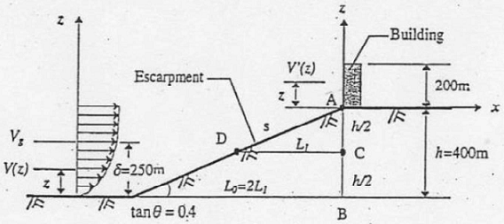
Q1. A 200m high tall building is to be built on an escarpment as shown in the below figure. The height of the escarpment is 400m and its windward slope is 0.4. Suppose the upstream is over an open terrain in Hong Kong of the power exponent of 0.19 and the meanhourly wind speed is 30m/s at 10m height.
Calculate the Loads at the location of the building at 10m, 100m and 200m heights?
By use the method stipulated in Hong Kong Wind Code and try to made your Comments.
Q2. As wind load have great effect on tall buildings, discuss some methods to resist or manage the wind load with consideration on the use in the building design.
Analyse the relationship between building form and wind loading.
Calculate and size the type of lateral stiffening required to resist wind loading for a given structure.
Q3. A simply supported beam has an effective span of 9.5m and is subjected to a characteristic dead load of 20 kN/mand a characteristic imposed load of 25 kN/m. The clear span of the beam is 9m. Calculate the bending shear reinforcement for the beam.
Determine for deflection of the beam by using span-effective depth ratio approach.
Given that:-
(a) The overall size of the beam is 400 x 700 mm (deep).
(b) The nominal cover = 30 mm.
(c) fcu = 35 N/mm2, fy = 460 N/mm2, fyv = 250 N/mm2.
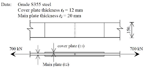
Q4. Evaluate the structural connections of the two main plates together as shown below, subjected to an ultimate tensile force of 700kN, with cover plates at both sides of the main plates using welded connection.
Discuss the relationship between bending, shear and deflection.
Critical evaluate different materials and their structural efficiency in managing bending, shear and deflection.
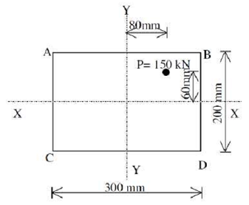
Q5. A 300 x 200 short column carries a compressive load of 150 kN acting at an eccentricity of 60 mm to the x-x axis and 80 mm to the y-y axis as shown in the below figure.
Calculate the axial load, bending load and combined load and all four corners A, B, C and D.
Q6. A short RC column has a 300 x 500 mm section and is subjected to an ultimate axial load of 4000 kN and a design bending moment of 300 kNm about its major axis. Design the area of reinforcement required.
Given that: (i) Nominal cover = 35 mm; (ii) Links size =10 mm; (iii) fcu = 35 N/mm2, fy = 460 N/mm2.
Discuss the benefits of using Building Information Modelling in the design workflow.
Assess the most effective foundation type for a given scenario in terms of ease and speed of construction, economics, safety and environmental factors.
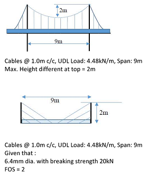
Q7. According to the above sketches, Prepare design the reaction forces for the suspension bridge and cable-stayed bridge, also the required diameter of the cable necessary for the Main Cable and Suspenders for suspension bridge and the Main Cable for Cable-stayed Bridge.
Q8. Base on the result obtained from above. Discuss the difference between suspension bridge compare with the cable-stayed bridge?
Design a simple tensile structure for a given scenario.
Compare tensile structural solutions to a given scenario.
Using calculations as well as other research, justify the choice of a tensile structure solution for a given scenario.