Reference no: EM132310699
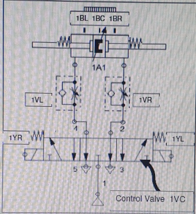
The figure above shows a silting-centred pneumatic cylinder controlled by a PLC. Indications from the figure are as follows:
• 1BL - Electronic position sensor, left
• 1BC - Eleetrtnic position sensor. centre
• 1BR - Eleetrinie position sensor. ri211t
• 1A1 - Double acting cylinder. double ended piston rod. spring centred, adjustable cushioning on both sides. position detection
• 1VL - Adjustable exhaust throttle, speed moving left
• 1VR - Adjustable exhaust throttle, speed moving right
• IVC - 5/3 Control Valve, spring centred, centre exhausted, 2 x solenoids 1 YL & I YR, exhaust terminals (3, 5) that is open without any silencers
• Operation:
• I YL energised - Solenoid, pressurize right-, exhaust left chamber, piston moves left
• None energised - Centre, Spring-return at both sides
• 1YR energised - Solenoid, pressurize left-, exhaust right chamber, piston moves right
Question 1:
a) List all your assumptions.
b) Write a PLC program in LD to implement the specified behaviour of the pneumatic cylinder.
c) Provide evidence in the form of appropriate, neat visualization to proof that your circuit operates as specified.
Attachment:- Assignment.rar