Reference no: EM132013953
Lab 1: IP Addressing Basics
Objective
- Name the five different classes of IP addresses
- Describe the characteristics and use of the different IP address classes
- Identify the class of an IP address based on the network number
- Determine which part, or octet, of an IP address is the network ID and which part is the host ID
- Identify valid and invalid IP host addresses based on the rules of IP addressing
- Define the range of addresses and default subnet mask for each class
Background / Preparation
This lab exercise helps develop an understanding of IP addresses and how TCP/IP networks operate. It is primarily a written lab exercise. However, it would be worthwhile to review some real network IP addresses using the command line utilities ipconfig for Windows. IP addresses are used to uniquely identify individual TCP/IP networks and hosts, such as computers and printers, on those networks in order for devices to communicate. Workstations and servers on a TCP/IP network are called hosts and each has a unique IP address. This address is referred to as its host address. TCP/IP is the most widely used protocol in the world. The Internet or World Wide Web only uses IP addressing. In order for a host to access the Internet, it must have an IP address.
In its basic form, the IP address has two parts:
- A network address
- A host address
The network portion of the IP address is assigned to a company or organization by the Internet Network Information Center (InterNIC). Routers use the IP address to move data packets between networks. IP addresses are 32 bits long according to the current version IPv4 and are divided into 4 octets of 8 bits each. They operate at the network layer (Layer 3) of the Open System Interconnection (OSI) model, which is the Internet layer of the TCP/IP model. IP addresses are assigned in the following ways:
- Statically - manually, by a network administrator
- Dynamically - automatically, by a Dynamic Host Configuration Protocol (DHCP) server
The IP address of a workstation, or host is a logical address, meaning it can be changed. The Media Access Control (MAC) address of the workstation is a 48-bit physical address. This address is burned into the network interface card (NIC) and cannot change unless the NIC is replaced. The combination of the logical IP address and the physical MAC address helps route packets to their proper destination.
There are five different classes of IP addresses, and depending on the class, the network and host part of the address will use a different number of bits. In this lab, different classes of IP addresses will be worked with and to help become familiar with the characteristics of each. The understanding of IP addresses is critical to the understanding of TCP/IP and internetworks in general. The following resources are required:
- PC workstation with Windows installed
- Access to the Windows Calculator
Step 1: Review IP address classes and their characteristics
Address classes
There are five classes of IP addresses, A through E. Only the first three classes are used commercially. A Class A network address is discussed in the table to get started. The first column is the class of IP address. The second column is the first octet, which must fall within the range shown for a given class of addresses. The Class A address must start with a number between 1 and 126. The first bit of a Class A address is always a zero, meaning the High Order Bit (HOB) or the 128 bit cannot be used. 127 is reserved for loopback testing. The first octet alone defines the network ID for a Class A network address.
Default subnet mask
The default subnet mask uses all binary ones, decimal 255, to mask the first 8 bits of the Class A address. The default subnet mask helps routers and hosts determine if the destination host is on this network or another one. Because there are only 126 Class A networks, the remaining 24 bits, or 3
octets, can be used for hosts. Each Class A network can have 224, or over 16 million hosts. It is common to subdivide the network into smaller groupings called subnets by using a custom subnet mask, which is discussed in the next lab.
Network and host address
The network or host portion of the address cannot be all ones or all zeros. As an example, the Class A address of 118.0.0.5 is a valid IP address. The network portion, or first 8 bits, which are equal to 118, is not all zeros and the host portion, or last 24 bits, is not all zeros or all ones. If the host portion were all zeros, it would be the network address itself. If the host portion were all ones, it would be a broadcast for the network address. The value of any octet can never be greater than decimal 255 or binary 11111111.
|
Class
|
1st Octet Decimal Range
|
1st Octet High Order Bits
|
Network/Host ID (N=Network, H=Host)
|
Default Subnet Mask
|
Number of Networks
|
Hosts per Network (Usable Addresses)
|
|
A
|
1 - 126 *
|
0
|
N.H.H.H
|
255.0.0.0
|
126 (27 - 2)
|
16,777,214
(224 - 2)
|
|
B
|
128 - 191
|
10
|
N.N.H.H
|
255.255.0.0
|
16,382
(214 - 2)
|
65,534
(216 - 2)
|
|
C
|
192 - 223
|
110
|
N.N.N.H
|
255.255.255.0
|
2,097,150
(221 - 2)
|
254 (28 - 2)
|
|
D
|
224 - 239
|
1110
|
Reserved for Multicasting
|
|
E
|
240 - 254
|
11110
|
Experimental; used for research
|
Note: Class A address 127 cannot be used and is reserved for loopback and diagnostic functions.
Step 2: Determine basic IP addressing
Use the IP address chart and your knowledge of IP address classes to answer the following questions:
1. What is the decimal and binary range of the first octet of all possible Class B IP addresses?
Decimal: From: Binary: From:
To: To:
2. Which octet(s) represent the network portion of a Class C IP address?
3. Which octet(s) represent the host portion of a Class A IP address?
4. What is the maximum number of useable hosts with a Class C network address?
5. How many Class B networks are there?
6. How many hosts can each Class B network have?
7. How many octets are there in an IP address? How many bits per octet?
Step 3: Determine the host and network portions of the IP address
With the following IP host addresses, indicate the following:
- Class of each address
- Network address or ID
- Host portion
- Broadcast address for this network
- Default subnet mask
The host portion will be all zeros for the network ID. Enter just the octets that make up the host. The host portion will be all ones for a broadcast. The network portion of the address will be all ones for the subnet mask. Fill in the following table:
|
Host IP Address
|
Address Class
|
Network Address
|
Host Address
|
Network Broadcast Address
|
Default Subnet Mask
|
|
216.14.55.137
|
|
|
|
|
|
|
123.1.1.15
|
|
|
|
|
|
|
150.127.221.244
|
|
|
|
|
|
|
194.125.35.199
|
|
|
|
|
|
|
175.12.239.244
|
|
|
|
|
|
Step 4: Given an IP address of 142.226.0.15 and a subnet mask of 255.255.255.0, answer the following questions:
What is the binary equivalent of the second octet? What is the class of the address?
What is the network address of this IP address?
Is this a valid IP host address (Y/N)? Why or why not?
Step 5: Determine which IP host addresses are valid for commercial networks
For the following IP host addresses, determine which are valid for commercial networks and indicate why or why not. Valid means it could be assigned to any of the following:
- Workstation
- Server
- Printer
- Router interface
- Any other compatible device Fill in the following table:
|
IP Host Address
|
Valid Address? (Yes/No)
|
Why or Why Not
|
|
150.100.255.255
|
|
|
|
175.100.255.18
|
|
|
|
195.234.253.0
|
|
|
|
100.0.0.23
|
|
|
|
188.258.221.176
|
|
|
|
127.34.25.189
|
|
|
|
224.156.217.73
|
|
|
Lab 2: Establishing a Console Session with Router
Topology Diagram
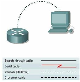
Step 1 Connect a Router and Computer with a Console Cable
Connect the console (rollover) cable to the console port on the router. Connect the other cable end to the PC with a DB-9 or DB-25 adapter to the COM 1 port.
Step 2 Power on devices
Step 3 Configure Terminal to Establish a Console Session with the Router.
COM1 Properties:
Bits per second = 9600
Data bits = 8 Parity = None Stop bits = 1
Flow control = None
Step 4 Continue without the setup dialog
a. The router prompts, "Continue with configuration dialog?" Enter no to continue without the setup dialog.
Command Modes and Router Identification
How does the router prompt look like? What does this prompt mean?
Step 1 Enter privileged EXEC mode
a. Enter enable at the user mode prompt.
Router>enable
b. If prompted for a password, enter the password class.
c. What prompt did the router display?
d. What does this prompt mean?
Step 2 Enter global configuration mode
a. Enter configure terminal at the privilege mode prompt.
Router#configure terminal
b. What prompt did the router display?
c. What does this prompt mean?
Step 3 Exit from global configuration mode
a. Enter exit at the config mode prompt.
Router(config)#exit
Step 4 Go back to user EXEC mode
a. Enter disable at the privileged mode prompt.
Router#disable
Step 5 Use the HELP feature
a. Enter the help command by typing the ? at the user EXEC router prompt.
Router>?
List eight available commands from the router response:
Step 6 Use the HELP feature at privileged EXEC mode
a. Enter enable mode by using the enable command
Router>enable [Enter]
b. Enter the help mode by typing a question mark (?) at the router privileged EXEC prompt.
Router#?
c. List ten (10) available commands from the router response:
Step 7 List the show commands
a. List all show commands by entering show ? at the router privileged EXEC prompt.
Router#show ?
b. Is running-config one of the available commands from this mode?
Step 8 Examine the running configuration
a. Router#show running-config
Step 9 Use the command history feature
a. Use the command history to see and reuse the previously entered commands. Press the up arrow or Ctrl-p to see the last entered command. Press it again to go to the command before that. Press the down arrow or Ctrl-n to go back through the list. This function lets the command history be viewed.
b. What appeared at the router prompt when the up arrow was pressed?
Step 10 Display IOS version and other important information with the "show version" command
a. Enter the show version command. The router will return information about the IOS that is running in RAM.
b. What is the IOS version?
c. What is the name of the system image (IOS) file?
d. Where was the router IOS image booted from?
e. What type of processor (CPU) and how much RAM does this router have?
_
f. How many Ethernet interfaces does this router have? How many serial interfaces?_
g. The router backup configuration file is stored in non-volatile random access memory (NVRAM). How much NVRAM does this router have?
h. The router operating system (IOS) is stored in Flash memory. How much Flash memory does
this router have? _
i. What is the configuration register set to? _
Step 11 Display the time and date for the router
a. Enter the show clock command. What information is displayed? _
Step 12 Display a cached list of host names and addresses
a. Enter the show hosts command. What information is displayed with show hosts?
Step 13 Display users who are connected to the router
a. Enter the show users command. What information is displayed with show users?
Step 14 Show the router ARP table
a. Enter the show arp command at the router prompt. What is the ARP table?
Step 15 Show information about the Flash memory device
a. Enter show flash at the router prompt.
b. How much Flash memory is available and used?
_
c. What is the file that is stored in Flash memory?
d. What is the size in bytes of the Flash memory?
Simple Router configuration
Step 1 Enter global configuration mode
a. Enter configure terminal at the privilege EXEC mode prompt.
Step 2 Enter a hostname of GAD for this router
a. Enter hostname GAD at the prompt.
Router(config)#hostname GAD
b. What prompt did the router display?
Step 3 Configure console password
Configure the console password on the router and exit from line console:
GAD(config)#line console 0 GAD(config-line)#password cisco GAD(config-line)#login GAD(config-line)#exit
Step 4 Configure telnet passwords
Configure the password on the virtual terminal lines and exit line mode:
GAD(config)#line vty 0 4 GAD(config-line)#password cisco GAD(config-line)#login GAD(config-line)#exit
Step 5 Configure the enable password
GAD(config)#enable password cisco
GAD(config)#exit
Step 6 Return to the user EXEC mode
GAD#disable
Step 7 Enter the privileged EXEC mode again
This time a prompt for a password will show. Enter cisco
GAD>enable Password:cisco
Step 8 Return to the configuration mode GAD#configure terminal
Step 9 Configure the enable secret password
GAD(config)#enable secret class
GAD(config)#exit
Note: Remember the enable secret password is encrypted from the configuration view. Also do not type enable secret password class, or the secret password will be password, not
class. The enable password is unencrypted and can be viewed from the configuration.
Step 10 Return to the user EXEC mode
GAD#disable
Step 11 Enter the privileged EXEC mode again
A prompt for a password will show. Enter cisco. If it fails, continue until the bad secrets message is displayed: GAD>enable
Password:cisco
Password:cisco Password:cisco
% Bad secrets
Configuring Message-of-the-Day (MOTD)
Step 1 Enter Global Configuration mode
a. Enter configure terminal at the router prompt. Notice the change in the router prompt.
Step 2 Display help for the banner motd command
a. Enter banner motd ? at the router prompt.
b. What is the character called that is used to indicate the beginning and end of the banner?
Step 3 Choose an appropriate MOTD
a. The login banner should be a warning not to attempt login unless authorized. In the following space, enter an appropriate warning banner. The message can contain any printable character as well as spaces and carriage returns.
Step 4 Enter the desired banner message
a. From the global configuration mode enter banner motd # message #. The "#" signs are used as delimiters and the "message" is the banner message chosen in the previous step.
Step 5 Test the MOTD display
a. Exit the console session. Reenter the router to display the message-of-the-day. This is done by pressing the Enter key. This will display the message entered into the configuration.
Step 6 Verify the MOTD by looking at the router configuration
a. Enter the show running-config command.
b. How does the banner MOTD show in the configuration listing?
Configuring an Ethernet Interface
Step 1 Configure the FastEthernet 0/0 interface
Note: The designation for the first Ethernet interface on the router will vary. It may be ethernet 0, fastethernet 0 or fastethernet 0/0 depending on the type of router.
GAD(config)#interface fastEthernet 0/0
GAD(config-if)#ip address 192.168.14.1 255.255.255.0
GAD(config-if)#no shutdown
GAD(config-if)#exit GAD (config)#exit
Note: Once interface configuration mode is entered, note the IP address of the interface. Enter the subnet mask.
The command no shutdown turns on the interface.
Shutdown is when the interface is off.
Step 2 Display FastEthernet 0/0s configuration information
GAD#show interface fastethernet 0/0
Note: This will show the details of the Ethernet interface.
a. List at least three details discovered by issuing this command.
b. FastEthernet0/0 is _. Line protocol is _ .
c. Internet address is .
d. Encapsulation
e. To what OSI layer is the "Encapsulation" referring?
Configuring a Serial Interface
Step 1 Configure serial interface Serial 0/0
From global configuration mode, configure serial interface Serial 0/0 on Router GAD
GAD(config)#interface serial 0/0
GAD(config-if)#ip address 192.168.15.1 255.255.255.0
GAD(config-if)#clock rate 56000 GAD(config-if)#no shutdown GAD(config-if)#exit GAD(config)#exit
Note: Once the interface configuration mode is entered, note the IP address of the interface. Enter the
subnet mask. Enter the clock rate only on the DCE side of the device.
Step 2 Display information about Serial0/0 interface on GAD
a. Enter the command show interface serial 0/0 on GAD.
GAD#show interface serial 0/0
This will show the details of interface serial 0/0.
b. List at least three details discovered by issuing this command.
c. Serial0/0 is . Line protocol is .
d. Internet address is .
e. Encapsulation
f. To what OSI layer is the "Encapsulation" referring?
g. If the Serial interface was configured, why did the show interface serial 0/0 say that the interface is down?
Step 3 Save the configuration
a. Save the running configuration to the startup configuration at the privileged EXEC mode.
GAD#copy running-config startup-config
Note: Save the running configuration for the next time that the router is restarted. The router can be restarted either by a software reload command or a power shutdown. The running configuration will be lost if the running configuration is not saved. The router uses the startup configuration when the router is started.
Configuring Interface Descriptions
Step 1 Enter Interface Configuration mode
a. Enter interface serial 0/0 at the global configuration prompt. Refer to interface chart. What does the router prompt look like in interface configuration mode?
Step 2 Display help for the description command
a. Enter description ? at the router prompt.
What is the maximum number of characters in an interface description?
Step 3 Choose a description for the interface
a. An interface description includes the purpose and location of the interface, other devices or locations connected to the interface, and circuit identifiers. Descriptions help the support personnel better understand the scope of problems related to an interface. Descriptions also allow for a faster resolution of problems.
b. Enter the description text. Then enter Ctrl-z or type end to return to the privileged EXEC mode.
Note: this would be the same as typing exit to leave the interface configuration mode and exit
again to leave Global Configuration mode. This is a keyboard shortcut.
Configuring Host Tables
Background/Preparation
IP host tables allow a router to use names to identify all of the attached interfaces on that router. These names can be used in place of an IP address in commands that use IP addresses to identify a location such as ping or Telnet.
a. From the global configuration mode, enter the command ip host followed by the name of each router in the network, as well as all of the IP addresses of the interfaces on each of the routers.
For example to name the GAD router accessible from BHM by the name "G", enter:
BHM(config)#ip host G 172.16.0.1 172.17.0.1
Completing the lab
Step 1 View your router configuration
a. to view running-configuration, enter
GAD#show running-configuration
b. to view saved configuration which is in file "startup-configuration", enter
GAD#show startup-configuration
Step 2 Erase your router configuration
If startup-configuration is not empty you have to erase it.
GAD#erase startup-configuration
Note: You can ensure that configuration is deleted by entering "show startup-configuration" again.
Step 3 Turn off the router and disconnect attached cables
Lab 3: Basic Router Configuration II
Topology Diagram
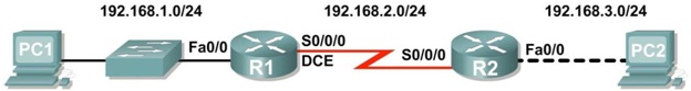
Addressing Table
|
Device
|
Interface
|
IP Address
|
Subnet Mask
|
Def. Gateway
|
|
R1
|
Fa0/0
|
192.168.1.1
|
255.255.255.0
|
N/A
|
|
S0/0/0
|
192.168.2.1
|
255.255.255.0
|
N/A
|
|
R2
|
Fa0/0
|
192.168.3.1
|
255.255.255.0
|
N/A
|
|
S0/0/0
|
192.168.2.2
|
255.255.255.0
|
N/A
|
|
PC1
|
N/A
|
192.168.1.10
|
255.255.255.0
|
192.168.1.1
|
|
PC2
|
N/A
|
192.168.3.10
|
255.255.255.0
|
192.168.3.1
|
Learning Objectives
Upon completion of this lab, you will be able to:
- Cable a network according to the Topology Diagram.
- Erase the startup configuration and reload a router to the default state.
- Perform basic configuration tasks on a router.
- Configure and activate Ethernet interfaces.
- Test and verify configurations.
- Reflect upon and document the network implementation.
Scenario
In this lab activity, you will create a network that is similar to the one shown in the Topology Diagram. Begin by cabling the network as shown in the Topology Diagram. You will then perform the initial router configurations required for connectivity. Use the IP addresses that are provided in the Topology Diagram to apply an addressing scheme to the network devices. When the network configuration is complete, examine the routing tables to verify that the network is operating properly.
Task 1: Cable the Network.
Cable a network that is similar to the one in the Topology Diagram. The output used in this lab is from 1841 routers. You can use any current router in your lab as long as it has the required interfaces as shown in the topology. Be sure to use the appropriate type of Ethernet cable to connect from host to switch, switch to router, and host to router. Be sure to connect the serial DCE cable to router R1 and the serial DTE cable to router R2.
Answer the following questions:
What type of cable is used to connect the Ethernet interface on a host PC to the Ethernet interface on a switch?
What type of cable is used to connect the Ethernet interface on a switch to the Ethernet interface on a router?
What type of cable is used to connect the Ethernet interface on a router to the Ethernet interface on a host PC?
Task 2: Perform Basic Configuration of Router R1.
Step 1: Establish a HyperTerminal session to router R1.
Step 2: Enter privileged EXEC mode.
Router>enable Router#
Step 3: Enter global configuration mode.
Router#configure terminal
Enter configuration commands, one per line. End with CNTL/Z. Router(config)#
Step 4: Configure the router name as R1.
Enter the command hostname R1 at the prompt.
Router(config)#hostname R1
R1(config)#
Step 5: Disable DNS lookup.
Disable DNS lookup with the no ip domain-lookup command.
R1(config)#no ip domain-lookup
R1(config)#
Why would you want to disable DNS lookup in a lab environment?
What would happen if you disabled DNS lookup in a production environment?
Step 6: Configure the EXEC mode password.
Configure the EXEC mode password using the enable secret password command. Use class for the password.
R1(config)#enable secret class
R1(config)#
Why is it not necessary to use the enable password password command?
Step 7: Configure a message-of-the-day banner.
Configure a message-of-the-day banner using the banner motd command.
R1(config)#banner motd &
Enter TEXT message. End with the character '&'.
********************************
!!!AUTHORIZED ACCESS ONLY!!!
******************************** &
R1(config)#
When does this banner display?
Why should every router have a message-of-the-day banner?
Step 8: Configure the console password on the router.
Use cisco as the password. When you are finished, exit from line configuration mode.
R1(config)#line console 0 R1(config-line)#password cisco R1(config-line)#login R1(config-line)#exit R1(config)#
Step 9: Configure the password for the virtual terminal lines.
Use cisco as the password. When you are finished, exit from line configuration mode.
R1(config)#line vty 0 4 R1(config-line)#password cisco R1(config-line)#login R1(config-line)#exit R1(config)#
Step 10: Configure the FastEthernet0/0 interface.
Configure the FastEthernet0/0 interface with the IP address 192.168.1.1/24.
R1(config)#interface fastethernet 0/0
R1(config-if)#ip address 192.168.1.1 255.255.255.0
R1(config-if)#no shutdown
%LINK-5-CHANGED: Interface FastEthernet0/0, changed state to up
%LINEPROTO-5-UPDOWN: Line protocol on Interface FastEthernet0/0, changed state to up
R1(config-if)#
Step 11: Configure the Serial0/0/0 interface.
Configure the Serial0/0/0 interface with the IP address 192.168.2.1/24. Set the clock rate to 64000.
Note: The purpose of the clock rate command is explained in Chapter 2: Static Routes.
R1(config-if)#interface serial 0/0/0
R1(config-if)#ip address 192.168.2.1 255.255.255.0
R1(config-if)#clock rate 64000 R1(config-if)#no shutdown R1(config-if)#
Note: The interface will be activated until the serial interface on R2 is configured and activated
Step 12: Return to privileged EXEC mode.
Use the end command to return to privileged EXEC mode.
R1(config-if)#end R1#
Step 13: Save the R1 configuration.
Save the R1 configuration using the copy running-config startup-config command.
R1#copy running-config startup-config
Building configuration... [OK]
R1#
What is a shorter version of this command?
Task 3: Perform Basic Configuration of Router R2.
Step 1: For R2, repeat Steps 1 through 9 from Task 2. Step 2: Configure the Serial 0/0/0 interface.
Configure the Serial 0/0/0 interface with the IP address 192.168.2.2/24.
R2(config)#interface serial 0/0/0
R2(config-if)#ip address 192.168.2.2 255.255.255.0
R2(config-if)#no shutdown
%LINK-5-CHANGED: Interface Serial0/0/0, changed state to up
%LINEPROTO-5-UPDOWN: Line protocol on Interface Serial0/0/0, changed state to up
R2(config-if)#
Step 3: Configure the FastEthernet0/0 interface.
Configure the FastEthernet0/0 interface with the IP address 192.168.3.1/24.
R2(config-if)#interface fastethernet 0/0 R2(config-if)#ip address 192.168.3.1 255.255.255.0 R2(config-if)#no shutdown
%LINK-5-CHANGED: Interface FastEthernet0/0, changed state to up
%LINEPROTO-5-UPDOWN: Line protocol on Interface FastEthernet0/0, changed state to up
R2(config-if)#
Step 4: Return to privileged EXEC mode.
Use the end command to return to privileged EXEC mode.
R2(config-if)#end R2#
Step 5: Save the R2 configuration.
Save the R2 configuration using the copy running-config startup-config command.
R2#copy running-config startup-config
Building configuration... [OK]
R2#
Task 4: Configure IP Addressing on the Host PCs.
Step 1: Configure the host PC1.
Configure the host PC1 that is attached to R1 with an IP address of 192.168.1.10/24 and a default gateway of 192.168.1.1.
Step 2: Configure the host PC2.
Configure the host PC2 that is attached to R2 with an IP address of 192.168.3.10/24 and a default gateway of 192.168.3.1.
Task 5: Verify and Test the Configurations.
Step 1: Verify that routing tables have the following routes using the show ip route command.
The show ip route command and output will be thoroughly explored in upcoming chapters. For now, you are interested in seeing that both R1 and R2 have two routes. Both routes are designated with a C. These are the directly connected networks that were activated when you configured the interfaces on each router. If you do not see two routes for each router as shown in the following output, proceed to Step 2.
R1#show ip route
Codes: C - connected, S - static, R - RIP, M - mobile, B - BGP
D - EIGRP, EX - EIGRP external, O - OSPF, IA - OSPF inter area N1 - OSPF NSSA external type 1, N2 - OSPF NSSA external type 2 E1 - OSPF external type 1, E2 - OSPF external type 2
i - IS-IS, su - IS-IS summary, L1 - IS-IS level-1, L2 - IS-IS level-2 ia - IS-IS inter area, * - candidate default, U - per-user static route o - ODR, P - periodic downloaded static route
Gateway of last resort is not set
C 192.168.1.0/24 is directly connected, FastEthernet0/0 C 192.168.2.0/24 is directly connected, Serial0/0/0
------------------------
R2#show ip route
Codes: C - connected, S - static, R - RIP, M - mobile, B - BGP
D - EIGRP, EX - EIGRP external, O - OSPF, IA - OSPF inter area N1 - OSPF NSSA external type 1, N2 - OSPF NSSA external type 2 E1 - OSPF external type 1, E2 - OSPF external type 2
i - IS-IS, su - IS-IS summary, L1 - IS-IS level-1, L2 - IS-IS level-2 ia - IS-IS inter area, * - candidate default, U - per-user static route o - ODR, P - periodic downloaded static route
Gateway of last resort is not set
C 192.168.2.0/24 is directly connected, Serial0/0/0
C 192.168.3.0/24 is directly connected, FastEthernet0/0
Step 2: Verify interface configurations.
Another common problem is router interfaces that are not configured correctly or not activated. Use the show ip interface brief command to quickly verify the configuration of each router's interfaces. Your output should look similar to the following:
R1#show ip interface brief
Interface IP-Address OK? Method Status Protocol FastEthernet0/0 192.168.1.1 YES manual up up
FastEthernet0/1 unassigned YES unset administratively down down
Serial0/0/0 192.168.2.1 YES manual up up
Serial0/0/1 unassigned YES unset administratively down down
Vlan1 unassigned YES manual administratively down down
|
R2#show ip interface
Interface
|
brief
IP-Address
|
OK?
|
Method Status
|
Protocol
|
|
FastEthernet0/0
|
192.168.3.1
|
YES
|
manual up
|
up
|
|
FastEthernet0/1 unassigned YES unset administratively down down
|
|
Serial0/0/0
|
192.168.2.2
|
YES
|
manual up
|
up
|
|
Serial0/0/1
|
unassigned
|
YES
|
unset down
|
down
|
| Vlan1 |
unassigned |
YES |
manual administratively |
down down |
If both interfaces are up and up, then both routes will be in the routing table. Verify this again by using the
show ip route command.
Step 3: Test connectivity.
Test connectivity by pinging from each host to the default gateway that has been configured for that host. From the host attached to R1, is it possible to ping the default gateway?
From the host attached to R2, is it possible to ping the default gateway?
If the answer is no for any of the above questions, troubleshoot the configurations to find the error using the following systematic process:
1. Check the PCs.
Are they physically connected to the correct router? (Connection could be through a switch or directly.)
Are link lights blinking on all relevant ports?
2. Check the PC configurations.
Do they match the Topology Diagram?
3. Check the router interfaces using the show ip interface brief command. Are the interfaces up and up?
If your answer to all three steps is yes, then you should be able to successfully ping the default gateway.
Step 4: Test connectivity between router R1 and R2.
From the router R1, is it possible to ping R2 using the command ping 192.168.2.2?
From the router R2, is it possible to ping R1 using the command ping 192.168.2.1?
If the answer is no for the questions above, troubleshoot the configurations to find the error using the following systematic process:
1. Check the cabling.
Are the routers physically connected?
Are link lights blinking on all relevant ports?
2. Check the router configurations.
Do they match the Topology Diagram?
Did you configure the clock rate command on the DCE side of the link?
3. Check the router interfaces using the show ip interface brief command. Are the interfaces "up" and "up"?
If your answer to all three steps is yes, then you should be able to successfully ping from R2 to R1 and from R2 to R3.
Task 6: Reflection
Step 1: Attempt to ping from the host connected to R1 to the host connected to R2.
This ping should be unsuccessful.
Step 2: Attempt to ping from the host connected to R1 to router R2.
This ping should be unsuccessful.
Step 3: Attempt to ping from the host connected to R2 to router R1.
This ping should be unsuccessful.
What is missing from the network that is preventing communication between these devices?
Task 7: Documentation
On each router, capture the following command output to a text (.txt) file and save for future reference.
- show running-config
- show ip route
- show ip interface brief
If you need to review the procedures for capturing command output, refer to Lab 1.5.1, "Cabling a Network and Basic Router Configuration."
Lab 4: Basic Static Route Configuration
Topology Diagram
Addressing Table
|
Device
|
Interface
|
IP Address
|
Subnet Mask
|
Default Gateway
|
|
R1
|
Fa0/0
|
172.16.3.1
|
255.255.255.0
|
N/A
|
|
S0/0/0
|
172.16.2.1
|
255.255.255.0
|
N/A
|
|
R2
|
Fa0/0
|
172.16.1.1
|
255.255.255.0
|
N/A
|
|
S0/0/0
|
172.16.2.2
|
255.255.255.0
|
N/A
|
|
S0/0/1
|
192.168.1.2
|
255.255.255.0
|
N/A
|
|
R3
|
FA0/0
|
192.168.2.1
|
255.255.255.0
|
N/A
|
|
S0/0/1
|
192.168.1.1
|
255.255.255.0
|
N/A
|
|
PC1
|
NIC
|
172.16.3.10
|
255.255.255.0
|
172.16.3.1
|
|
PC2
|
NIC
|
172.16.1.10
|
255.255.255.0
|
172.16.1.1
|
|
PC3
|
NIC
|
192.168.2.10
|
255.255.255.0
|
192.168.2.1
|
Learning Objectives
Upon completion of this lab, you will be able to:
- Cable a network according to the Topology Diagram.
- Erase the startup configuration and reload a router to the default state.
- Perform basic configuration tasks on a router.
- Interpret debug ip routing output.
- Configure and activate Serial and Ethernet interfaces.
- Test connectivity.
- Gather information to discover causes for lack of connectivity between devices.
- Configure a static route using an intermediate address.
- Configure a static route using an exit interface.
- Compare a static route with intermediate address to a static route with exit interface.
- Configure a default static route.
- Configure a summary static route.
- Document the network implementation.
Scenario
In this lab activity, you will create a network that is similar to the one shown in the Topology Diagram. Begin by cabling the network as shown in the Topology Diagram. You will then perform the initial router configurations required for connectivity. Use the IP addresses that are provided in the Addressing Table to apply an addressing scheme to the network devices. After completing the basic configuration, test connectivity between the devices on the network. First test the connections between directly connected devices, and then test connectivity between devices that are not directly connected. Static routes must be configured on the routers for end-to-end communication to take place between the network hosts. You will configure the static routes that are needed to allow communication between the hosts. View the routing table after each static route is added to observe how the routing table has changed.
Task 1: Cable, Erase, and Reload the Routers.
Step 1: Cable a network that is similar to the one in the Topology Diagram.
Step 2: Clear the configuration on each router.
Clear the configuration on each of the routers using the erase startup-config command and then
reload the routers. Answer no if asked to save changes.
Task 2: Perform Basic Router Configuration.
Note: If you have difficulty with any of the commands in this task, see Lab 1.5.1: Cabling a Network and Basic Router Configuration.
Step 1: Use global configuration commands.
On the routers, enter global configuration mode and configure the basic global configuration commands including:
- hostname
- no ip domain-lookup
- enable secret
Step 2: Configure the console and virtual terminal line passwords on each of the routers.
- password
- login
Step 3: Add the logging synchronous command to the console and virtual terminal lines.
This command is very helpful in both lab and production environments and uses the following syntax:
Router(config-line)#logging synchronous
To synchronize unsolicited messages and debug output with solicited Cisco IOS software output and prompts for a specific console port line, auxiliary port line, or virtual terminal line, we can use the logging synchronous line configuration command. In other words, the logging synchronous command prevents IOS messages delivered to the console or Telnet lines from interrupting your keyboard input.
For example, you may have already experienced something similar to the following example:
Note: Do not configure R1 interfaces yet.
R1(config)#interface fastethernet 0/0
R1(config-if)#ip address 172.16.3.1 255.255.255.0
R1(config-if)#no shutdown
R1(config-if)#description
*Mar 1 01:16:08.212: %LINK-3-UPDOWN: Interface FastEthernet0/0, changed state to up
*Mar 1 01:16:09.214: %LINEPROTO-5-UPDOWN: Line protocol on Interface FastEthernet0/0, changed state to up
R1(config-if)#
The IOS sends unsolicited messages to the console when you activate an interface with the no shutdown command. However, the next command you enter (in this case, description) is interrupted by these messages. The logging synchronous command solves this problem by copying the command entered up to that point down to the next router prompt.
R1(config)#interface fastethernet 0/0
R1(config-if)#ip address 172.16.3.1 255.255.255.0
R1(config-if)#no shutdown
R1(config-if)#description
*Mar 1 01:28:04.242: %LINK-3-UPDOWN: Interface FastEthernet0/0, changed state to up
*Mar 1 01:28:05.243: %LINEPROTO-5-UPDOWN: Line protocol on Interface FastEthernet0/0, changed state to up
R1(config-if)#description <-- Keyboard input copied after message
R1 is shown here as an example. Add logging synchronous to the console and virtual terminal lines on all routers.
R1(config)#line console 0 R1(config-line)#logging synchronous R1(config-line)#line vty 0 4 R1(config-line)#logging synchronous
Step 4: Add the exec-timeout command to the console and virtual terminal lines.
To set the interval that the EXEC command interpreter waits until user input is detected, we can use the exec-timeout line configuration command. If no input is detected during the interval, the EXEC facility resumes the current connection. If no connections exist, the EXEC facility returns the terminal to the idle state and disconnects the incoming session. This command allows you to control the amount of time a console or virtual terminal line can be idle before the session is terminated. The syntax follows:
Router(config-line)#exec-timeout minutes [seconds]
Syntax description:
minutes-Integer that specifies the number of minutes.
seconds-(Optional) Additional time intervals in seconds.
In a lab environment, you can specify "no timeout" by entering the exec-timeout 0 0 command. This command is very helpful because the default timeout for lines is 10 minutes. However, for security purposes, you would not normally set lines to "no timeout" in a production environment.
R1 is shown here as an example.
Add exec-timeout 0 0 to console and virtual terminal lines on all routers.
R1(config)#line console 0
R1(config-line)#exec-timeout 0 0
R1(config-line)#line vty 0 4
R1(config-line)#exec-timeout 0 0
Task 3: Interpreting Debug Output.
Note: If you already configured IP addressing on R1, please remove all interface commands now before proceeding. R1, R2 and R3 should be configured through the end of Task 2 without any interface configurations.
Step 1: On R1 from privileged EXEC mode, enter the debug ip routing command.
R1#debug ip routing
IP routing debugging is on
The debug ip routing command shows when routes are added, modified, and deleted from the routing table. For example, every time you successfully configure and activate an interface, Cisco IOS adds a route to the routing table. We can verify this by observing output from the debug ip routing command.
Step 2: Enter interface configuration mode for R1's LAN interface.
R1#configure terminal
Enter configuration commands, one per line. End with CNTL/Z. R1(config)#interface fastethernet 0/0
Configure the IP address as specified in the Topology Diagram.
R1(config-if)#ip address 172.16.3.1 255.255.255.0
is_up: 0 state: 6 sub state: 1 line: 1 has_route: False
As soon as you press the Enter key, Cisco IOS debug output informs you that there is now a route, but its state is False. In other words, the route has not yet been added to the routing table. Why did this occur and what steps should be taken to ensure that the route is entered into the routing table?
Step 3: Enter the command necessary to install the route in the routing table.
If you are not sure what the correct command is, review the discussion in "Examining Router Interfaces" which is discussed in Section 2.2, "Router Configuration Review."
After you enter the correct command, you should see debug output. Your output may be slightly different from the example below.
is_up: 1 state: 4 sub state: 1 line: 1 has_route: False RT: add 172.16.3.0/24 via 0.0.0.0, connected metric [0/0] RT: NET-RED 172.16.3.0/24
RT: NET-RED queued, Queue size 1
RT: interface FastEthernet0/0 added to routing table
%LINK-3-UPDOWN: Interface FastEthernet0/0, changed state to up is_up: 1 state: 4 sub state: 1 line: 1 has_route: True
%LINEPROTO-5-UPDOWN: Line protocol on Interface FastEthernet0/0, chan ged state to up
is_up: 1 state: 4 sub state: 1 line: 1 has_route: True
is_up: 1 state: 4 sub state: 1 line: 1 has_route: True
The new network you configured on the LAN interface is now added to the routing table, as shown in the highlighted output.
If you do not see the route added to the routing table, the interface did not come up. Use the following systematic process to troubleshoot your connection:
1. Check your physical connections to the LAN interface. Is the correct interface attached?
Your router may have more than one LAN interface. Did you connect the correct LAN interface?
An interface will not come up unless it detects a carrier detect signal at the Physical layer from another device. Is the interface connected to another device such as a hub, switch, or PC?
2. Check link lights. Are all link lights blinking?
3. Check the cabling. Are the correct cables connected to the devices?
4. Has the interface been activated or enabled?
If you can answer yes to all the proceeding questions, the interface should come up.
Step 4: Enter the command to verify that the new route is now in the routing table.
Your output should look similar to the following output. There should now be one route in the table for R1. What command did you use?
R1#
Codes: C - connected, S - static, I - IGRP, R - RIP, M - mobile, B - BGP
D - EIGRP, EX - EIGRP external, O - OSPF, IA - OSPF inter area
N1 - OSPF NSSA external type 1, N2 - OSPF NSSA external type 2
E1 - OSPF external type 1, E2 - OSPF external type 2, E - EGP
i - IS-IS, L1 - IS-IS level-1, L2 - IS-IS level-2, ia - IS-IS inter area
* - candidate default, U - per-user static route, o - ODR
P - periodic downloaded static route
Gateway of last resort is not set 172.16.0.0/24 is subnetted, 1 subnets
C 172.16.3.0 is directly connected, FastEthernet0/0
Step 5: Enter interface configuration mode for R1's WAN interface connected to R2.
R1#configure terminal
Enter configuration commands, one per line. End with CNTL/Z. R1(config)#interface Serial 0/0/0
Configure the IP address as specified in the Topology Diagram.
R1(config-if)#ip address 172.16.2.1 255.255.255.0
is_up: 0 state: 0 sub state: 1 line: 0 has_route: False
As soon as you press the Enter key, Cisco IOS debug output informs you that there is now a route, but its state is False. Because R1 is the DCE side of our lab environment, we must specify how fast the bits will be clocked between R1 and R2.
Step 6: Enter the clock rate command on R1.
You can specify any valid clocking speed. Use the "?" to find the valid rates. Here, we used 64000 bps.
R1(config-if)#clock rate 64000
is_up: 0 state: 0 sub state: 1 line: 0 has_route: False
Some IOS versions display the output shown above every 30 seconds. Why is the state of the route still
False? What step must you now take to make sure that the interface is fully configured?
Step 7: Enter the command necessary to ensure that the interface is fully configured.
If you are not sure what the correct command is, review the discussion in "Examining Router Interfaces," which is discussed in Section 2.2, "Router Configuration Review."
R1(config-if)#
After you enter the correct command, you should see debug output similar to the following example:
is_up: 0 state: 0 sub state: 1 line: 0 has_route: False
%LINK-3-UPDOWN: Interface Serial0/0/0, changed state to down
Unlike configuring the LAN interface, fully configuring the WAN interface does not always guarantee that the route will be entered in the routing table, even if your cable connections are correct. The other side of the WAN link must also be configured.
Step 8: If possible, establish a separate terminal session by consoling into R2 from another workstation. Doing this allows you to observe the debug output on R1 when you make changes on R2. You can also turn on debug ip routing on R2.
R2#debug ip routing
IP routing debugging is on
Enter interface configuration mode for R2's WAN interface connected to R1.
R2#configure terminal
Enter configuration commands, one per line. End with CNTL/Z. R2(config)#interface serial 0/0/0
Configure the IP address as specified in the Topology Diagram.
R2(config-if)#ip address 172.16.2.2 255.255.255.0
is_up: 0 state: 6 sub state: 1 line: 0
Step 9: Enter the command necessary to ensure that the interface is fully configured.
If you are not sure what the correct command is, review the discussion in "Examining Router Interfaces," which is discussed in Section 2.2, "Router Configuration Review."
R2(config-if)#
After you enter the correct command, you should see debug output similar to the following example:
is_up: 0 state: 4 sub state: 1 line: 0
%LINK-3-UPDOWN: Interface Serial0/0/0, changed state to up is_up: 1 state: 4 sub state: 1 line: 0
RT: add 172.16.2.0/24 via 0.0.0.0, connected metric [0/0]
RT: interface Serial0/0/0 added to routing table is_up: 1 state: 4 sub state: 1 line: 0
%LINEPROTO-5-UPDOWN: Line protocol on Interface Serial0/0/0, changed state to up
is_up: 1 state: 4 sub state: 1 line: 0
The new network that you configured on the LAN interface is now added to the routing table, as shown in the highlighted output.
If you do not see the route added to the routing table, the interface did not come up. Use the following systematic process to troubleshoot your connection:
1. Check your physical connections between the two WAN interfaces for R1 and R2. Is the correct interface attached?
Your router has more than one WAN interface. Did you connect the correct WAN interface?
An interface will not come up unless it detects a link beat at the Physical layer from another device. Is the interface connected to the other router's interface?
2. Check link lights. Are all link lights blinking?
3. Check the cabling. R1 must have the DCE side of the cable attached and R2 must have the DTE side of the cable attached. Are the correct cables connected to the routers?
4. Has the interface been activated or enabled?
If you can answer yes to all the proceeding questions, the interface should come up.
Step 10: Enter the command to verify that the new route is now in the routing table for R1 and R2.
Your output should look similar to the following output. There should now be two routes in the routing table for R1 and one route in the table for R2. What command did you use?
R1#
Codes: C - connected, S - static, R - RIP, M - mobile, B - BGP
D - EIGRP, EX - EIGRP external, O - OSPF, IA - OSPF inter area N1 - OSPF NSSA external type 1, N2 - OSPF NSSA external type 2 E1 - OSPF external type 1, E2 - OSPF external type 2
i - IS-IS, su - IS-IS summary, L1 - IS-IS level-1, L2 - IS-IS level-2 ia - IS-IS inter area, * - candidate default, U - per-user static route o - ODR, P - periodic downloaded static route
Gateway of last resort is not set 172.16.0.0/24 is subnetted, 2 subnets
C 172.16.2.0 is directly connected, Serial0/0/0
C 172.16.3.0 is directly connected, FastEthernet0/0
R2#
Codes: C - connected, S - static, I - IGRP, R - RIP, M - mobile, B - BGP D - EIGRP, EX - EIGRP external, O - OSPF, IA - OSPF inter area N1 - OSPF NSSA external type 1, N2 - OSPF NSSA external type 2
E1 - OSPF external type 1, E2 - OSPF external type 2, E - EGP
i - IS-IS, L1 - IS-IS level-1, L2 - IS-IS level-2, ia - IS-IS inter area
* - candidate default, U - per-user static route, o - ODR P - periodic downloaded static route
Gateway of last resort is not set 172.16.0.0/24 is subnetted, 1 subnets
C 172.16.2.0 is directly connected, Serial0/0/0
Step 11: Turn off debugging on both routers using either no debug ip routing or simply, undebug all.
R1(config-if)#end R1#no debug ip routing
IP routing debugging is off
Task 4: Finish Configuring Router Interfaces
Step 1: Configure Remaining R2 Interfaces
Finish configuring the remaining interfaces on R2 according to the Topology Diagram and Addressing Table.
Step 2: Configure R3 Interfaces
Console into R3 and configure the necessary interfaces according to the Topology Diagram and Addressing Table.
Task 5: Configure IP Addressing on the Host PCs.
Step 1: Configure the host PC2.
Configure the host PC1 with an IP address of 172.16.3.10/24 and a default gateway of 172.16.3.1.
Step 2: Configure the host PC2.
Configure the host PC2 with an IP address of 172.16.1.10/24 and a default gateway of 172.16.1.1.
Step 3: Configure the host PC3.
Configure the host PC3 with an IP address of 192.168.2.10/24 and a default gateway of 192.168.2.1.
Task 6: Test and Verify the Configurations.
Step 1: Test connectivity.
Test connectivity by pinging from each host to the default gateway that has been configured for that host. From the host PC1, is it possible to ping the default gateway?
From the host PC2, is it possible to ping the default gateway? From the host PC3, is it possible to ping the default gateway?
If the answer is no for any of these questions, troubleshoot the configurations to find the error using the following systematic process:
1. Check the cabling.
Are the PCs physically connected to the correct router? (Connection could be through a switch or directly)
Are link lights blinking on all relevant ports?
2. Check the PC configurations. Do they match the Topology Diagram?
3. Check the router interfaces using the show ip interface brief command. Are all relevant interfaces up and up?
If your answer to all three steps is yes, you should be able to successfully ping the default gateway.
Step 2: Use the ping command to test connectivity between directly connected routers.
From the router R2, is it possible to ping R1 at 172.16.2.1? From the router R2, is it possible to ping R3 at 192.168.1.1?
If the answer is no for any of these questions, troubleshoot the configurations to find the error using the following systematic process:
1. Check the cabling.
Are the routers physically connected?
Are link lights blinking on all relevant ports?
2. Check the router configurations.
Do they match the Topology Diagram?
Did you configure the clock rate command on the DCE side of the link?
3. Has the interface been activated or enabled?
4. Check the router interfaces using the show ip interface brief command. Are the interfaces up and up?
If your answer to all three steps is yes, you should be able to successfully ping from R2 to R1 and from R2 to R3.
Step 3: Use ping to check connectivity between devices that are not directly connected.
From the host PC3, is it possible to ping the host PC1? From the host PC3, is it possible to ping the host PC2? From the host PC2, is it possible to ping the host PC1? From the router R1, is it possible to ping router R3? These pings should all fail. Why?
Task 7: Gather Information.
Step 1: Check status of interfaces.
Check the status of the interfaces on each router with the command show ip interface brief. The following output is for R2.
R2#show ip interface brief
Interface IP-Address OK? Method Status Protocol
FastEthernet0/0 172.16.1.1 YES manual up up FastEthernet0/1 unassigned YES unset administratively down down Serial0/0/0 172.16.2.2 YES manual up up
Serial0/0/1 192.168.1.2 YES manual up up Vlan1 unassigned YES manual administratively down down
Are all of the relevant interfaces on each router activated (that is, in the up and up state)? How many interfaces are activated on R1 and R3?
Why are there three activated interfaces on R2?
Step 2: View the routing table information for all three routers.
R1#
Codes: C - connected, S - static, I - IGRP, R - RIP, M - mobile, B - BGP D - EIGRP, EX - EIGRP external, O - OSPF, IA - OSPF inter area N1 - OSPF NSSA external type 1, N2 - OSPF NSSA external type 2
E1 - OSPF external type 1, E2 - OSPF external type 2, E - EGP
i - IS-IS, L1 - IS-IS level-1, L2 - IS-IS level-2, ia - IS-IS inter area
* - candidate default, U - per-user static route, o - ODR P - periodic downloaded static route
Gateway of last resort is not set 172.16.0.0/24 is subnetted, 2 subnets
C 172.16.2.0 is directly connected, Serial0/0/0
C 172.16.3.0 is directly connected, FastEthernet0/0
What networks are present in the Topology Diagram but not in the routing table for R1?
R2#
Codes: C - connected, S - static, I - IGRP, R - RIP, M - mobile, B - BGP D - EIGRP, EX - EIGRP external, O - OSPF, IA - OSPF inter area N1 - OSPF NSSA external type 1, N2 - OSPF NSSA external type 2
E1 - OSPF external type 1, E2 - OSPF external type 2, E - EGP
i - IS-IS, L1 - IS-IS level-1, L2 - IS-IS level-2, * - candidate default U - per-user static route, o - ODR
Gateway of last resort is not set 172.16.0.0/24 is subnetted, 2 subnets
C 172.16.1.0 is directly connected, FastEthernet0/0 C 172.16.2.0 is directly connected, Serial0/0/0
C 192.168.1.0/24 is directly connected, Serial0/0/1
What networks are present in the Topology Diagram but not in the routing table for R2?
R3#
Codes: C - connected, S - static, I - IGRP, R - RIP, M - mobile, B - BGP D - EIGRP, EX - EIGRP external, O - OSPF, IA - OSPF inter area N1 - OSPF NSSA external type 1, N2 - OSPF NSSA external type 2
E1 - OSPF external type 1, E2 - OSPF external type 2, E - EGP
i - IS-IS, L1 - IS-IS level-1, L2 - IS-IS level-2, * - candidate default U - per-user static route, o - ODR
Gateway of last resort is not set
C 192.168.1.0/24 is directly connected, Serial0/0/1
C 192.168.2.0/24 is directly connected, FastEthernet0/0
What networks are present in the Topology Diagram but not in the routing table for R3?
Why are all the networks not in the routing tables for each of the routers?
What can be added to the network so that devices that are not directly connected can ping each other?
Task 8: Configure a Static Route Using a Next-Hop Address.
Step 1: To configure static routes with a next-hop specified, use the following syntax:
Router(config)# ip route network-address subnet-mask ip-address
- network-address:-Destination network address of the remote network to be added to the routing table.
- subnet-mask-Subnet mask of the remote network to be added to the routing table. The subnet mask can be modified to summarize a group of networks.
- ip-address-Commonly referred to as the next-hop router's IP address.
On the R3 router, configure a static route to the 172.16.1.0 network using the Serial 0/0/1 interface of R2 as the next-hop address.
R3(config)#ip route 172.16.1.0 255.255.255.0 192.168.1.2
R3(config)#
Step 2: View the routing table to verify the new static route entry.
Notice that the route is coded with an S, which means that the route is a static route.
R3#
Codes: C - connected, S - static, I - IGRP, R - RIP, M - mobile, B - BGP D - EIGRP, EX - EIGRP external, O - OSPF, IA - OSPF inter area N1 - OSPF NSSA external type 1, N2 - OSPF NSSA external type 2 E1 - OSPF external type 1, E2 - OSPF external type 2, E - EGP
i - IS-IS, L1 - IS-IS level-1, L2 - IS-IS level-2, * - candidate default
U - per-user static route, o - ODR Gateway of last resort is not set
172.16.0.0/24 is subnetted, 1 subnets S 172.16.1.0 [1/0] via 192.168.1.2
C 192.168.1.0/24 is directly connected, Serial0/0/1
C 192.168.2.0/24 is directly connected, FastEthernet0/0 R3#
With this route entered in the routing table, any packet that matches the first 24 left-most bits of 172.16.1.0/24 will be forwarded to the next-hop router at 192.168.1.2.
What interface will R3 use to forward packets to the 172.16.1.0/24 network?
Assume that the following packets have arrived at R3 with the indicated destination addresses. Will R3 discard the packet or forward the packet? If R3 forwards the packet, with what interface will R3 send the packet?
|
Packet
|
Destination IP
|
Discard or Forward?
|
Interface
|
|
1
|
172.16.2.1
|
|
|
|
2
|
172.16.1.10
|
|
|
|
3
|
192.168.1.2
|
|
|
|
4
|
172.16.3.10
|
|
|
|
5
|
192.16.2.10
|
|
|
Although R3 will forward packets to destinations for which there is a route, this does not mean that a packet will arrive safely at the final destination.
Step 3: Use ping to check connectivity between the host PC3 and the host PC2.
From the host PC3, is it possible to ping the host PC2?
These pings should fail. The pings will arrive at PC2 if you have configured and verified all devices through Task 6, "Gather Information." PC2 will send a ping reply back to PC3. However, the ping reply will be discarded at R2 because the R2 does not have a return route to the 192.168.2.0 network in the routing table.
Step 4: On the R2 router, configure a static route to reach the 192.168.2.0 network.
What is the next-hop address to which R2 would send a packet destined for the 192.168.2.0/24 network?
R2(config)#ip route 192.168.2.0 255.255.255.0
R2(config)#
Step 5: View the routing table to verify the new static route entry.
Notice that the route is coded with an S, which means the route is a static route.
R2#
Codes: C - connected, S - static, I - IGRP, R - RIP, M - mobile, B - BGP D - EIGRP, EX - EIGRP external, O - OSPF, IA - OSPF inter area N1 - OSPF NSSA external type 1, N2 - OSPF NSSA external type 2 E1 - OSPF external type 1, E2 - OSPF external type 2, E - EGP
i - IS-IS, L1 - IS-IS level-1, L2 - IS-IS level-2, * - candidate default
U - per-user static route, o - ODR Gateway of last resort is not set
172.16.0.0/24 is subnetted, 2 subnets
C 172.16.1.0 is directly connected, FastEthernet0/0 C 172.16.2.0 is directly connected, Serial0/0/0
C 192.168.1.0/24 is directly connected, Serial0/0/1 S 192.168.2.0/24 [1/0] via 192.168.1.1
R2#
Step 6: Use ping to check connectivity between the host PC3 and the host PC2.
From the host PC3, is it possible to ping the host PC2? This ping should be successful.
Task 9: Configure a Static Route Using an Exit Interface.
To configure static routes with an exit interface specified, use the following syntax:
Router(config)# ip route network-address subnet-mask exit-interface
- network-address-Destination network address of the remote network to be added to the routing table.
- subnet-mask-Subnet mask of the remote network to be added to the routing table. The subnet mask can be modified to summarize a group of networks.
- exit-interface-Outgoing interface that would be used in forwarding packets to the destination network.
Step 1: On the R3 router, configure a static route.
On the R3 router, configure a static route to the 172.16.2.0 network using the Serial 0/0/0 interface of the R3 router as the exit interface.
R3(config)# ip route 172.16.2.0 255.255.255.0 Serial0/0/1
R3(config)#
Step 2: View the routing table to verify the new static route entry.
R3#
Codes: C - connected, S - static, I - IGRP, R - RIP, M - mobile, B - BGP D - EIGRP, EX - EIGRP external, O - OSPF, IA - OSPF inter area N1 - OSPF NSSA external type 1, N2 - OSPF NSSA external type 2 E1 - OSPF external type 1, E2 - OSPF external type 2, E - EGP
i - IS-IS, L1 - IS-IS level-1, L2 - IS-IS level-2, * - candidate default
U - per-user static route, o - ODR Gateway of last resort is not set
172.16.0.0/24 is subnetted, 2 subnets S 172.16.1.0 [1/0] via 192.168.1.2
S 172.16.2.0 is directly connected, Serial0/0/1
C 192.168.1.0/24 is directly connected, Serial0/0/1
C 192.168.2.0/24 is directly connected, FastEthernet0/0 R3#
Use the show running-config command to verify the static routes that are currently configured on R3.
R3#show running-config
Building configuration...
<output omitted>
!
hostname R3
!
interface FastEthernet0/0
ip address 192.168.2.1 255.255.255.0
!
interface Serial0/0/0 no ip address shutdown
!
interface Serial0/0/1
ip address 192.168.1.1 255.255.255.0
!
ip route 172.16.1.0 255.255.255.0 192.168.1.2
ip route 172.16.2.0 255.255.255.0 Serial0/0/1
!
end
How would you remove either of these routes from the configuration?
Step 3: On the R2 router, configure a static route.
On the R2 router, configure a static route to the 172.16.3.0 network using the Serial 0/0/0 interface of the R2 router as the exit interface.
R2(config)# ip route 172.16.3.0 255.255.255.0 Serial0/0/0
R2(config)#
Step 4: View the routing table to verify the new static route entry.
R2#
Codes: C - connected, S - static, I - IGRP, R - RIP, M - mobile, B - BGP D - EIGRP, EX - EIGRP external, O - OSPF, IA - OSPF inter area N1 - OSPF NSSA external type 1, N2 - OSPF NSSA external type 2
E1 - OSPF external type 1, E2 - OSPF external type 2, E - EGP
i - IS-IS, L1 - IS-IS level-1, L2 - IS-IS level-2, * - candidate default U - per-user static route, o - ODR
Gateway of last resort is not set 172.16.0.0/24 is subnetted, 3 subnets
C 172.16.1.0 is directly connected, FastEthernet0/0 C 172.16.2.0 is directly connected, Serial0/0/0
S 172.16.3.0 is directly connected, Serial0/0/0 C 192.168.1.0/24 is directly connected, Serial0/0/1 S 192.168.2.0/24 [1/0] via 192.168.1.1
R2#
At this point, R2 has a complete routing table with valid routes to all five networks shown in the Topology Diagram.
Does this mean that R2 can receive ping replies from all destinations shown in the Topology Diagram? Why or why not?
Step 5: Use ping to check connectivity between the host PC2 and PC1.
This ping should fail because the R1 router does not have a return route to the 172.16.1.0 network in the routing table.
Task 10: Configure a Default Static Route.
In the previous steps, you configured the router for specific destination routes. But could you do this for every route on the Internet? No. The router and you would be overwhelmed. To minimize the size of the routing tables, add a default static route. A router uses the default static route when there is not a better, more specific route to a destination.
Instead of filling the routing table of R1 with static routes, we could assume that R1 is a stub router. This means that R2 is the default gateway for R1. If R1 has packets to route that do not belong to any of R1 directly connected networks, R1 should send the packet to R2. However, we must explicitly configure R1 with a default route before it will send packets with unknown destinations to R2. Otherwise, R1 discards packets with unknown destinations.
To configure a default static route, use the following syntax:
Router(config)#ip route 0.0.0.0 0.0.0.0 { ip-address | interface }
Step 1: Configure the R1 router with a default route.
Configure the R1 router with a default route using the Serial 0/0/0 interface of R1 as the next-hop interface.
R1(config)#ip route 0.0.0.0 0.0.0.0 172.16.2.2
R1(config)#
Step 2: View the routing table to verify the new static route entry.
R1#
Codes: C - connected, S - static, I - IGRP, R - RIP, M - mobile, B - BGP D - EIGRP, EX - EIGRP external, O - OSPF, IA - OSPF inter area N1 - OSPF NSSA external type 1, N2 - OSPF NSSA external type 2 E1 - OSPF external type 1, E2 - OSPF external type 2, E - EGP
i - IS-IS, L1 - IS-IS level-1, L2 - IS-IS level-2, * - candidate default U - per-user static route, o - ODR
Gateway of last resort is 172.16.2.2 to network 0.0.0.0 172.16.0.0/24 is subnetted, 2 subnets
C 172.16.2.0 is directly connected, Serial0/0/0
C 172.16.3.0 is directly connected, FastEthernet0/0 S* 0.0.0.0/0 [1/0] via 172.16.2.2
R1#
Note that the R1 router now has a default route, the gateway of last resort, and will send all unknown traffic out Serial 0/0/0, which is connected to R2.
Step 3: Use ping to check connectivity between the host PC2 and PC1.
From the host PC2, is it possible to ping PC1?
This ping should be successful this time because the R1 router can return the packet using the default route.
From the host PC3, is it possible to ping the host PC1?
Is there a route to the 172.16.3.0 network in the routing table on the R3 router?
Task 11: Configure a Summary Static Route.
We could configure another static route on R3 for the 172.16.3.0 network. However, we already have two static routes to 172.16.2.0/24 and 172.16.1.0/24. Because these networks are so close together, we can summarize them into one route. Again, doing this helps reduce the size of routing tables, which makes the route lookup process more efficient.
Looking at the three networks at the binary level, we can a common boundary at the 22nd bit from the left.
172.16.1.0 10101100.00010000.00000001.00000000
172.16.2.0 10101100.00010000.00000010.00000000
172.16.3.0 10101100.00010000.00000011.00000000
The prefix portion will include 172.16.0.0, because this would be the prefix if we turned off all the bits to the right of the 22nd bit.
Prefix 172.16.0.0
To mask the first 22 left-most bits, we use a mask with 22 bits turned on from left to right:
Bit Mask 11111111.11111111.11111100.00000000
This mask, in dotted-decimal format, is...
Mask 255.255.252.0
Step 1: Configure the summary static route on the R3 router.
The network to be used in the summary route is 172.16.0.0/22.
R3(config)#ip route 172.16.0.0 255.255.252.0 192.168.1.2
Step 2: Verify that the summary route is installed in the routing table.
R3#
Codes: C - connected, S - static, I - IGRP, R - RIP, M - mobile, B - BGP D - EIGRP, EX - EIGRP external, O - OSPF, IA - OSPF inter area N1 - OSPF NSSA external type 1, N2 - OSPF NSSA external type 2 E1 - OSPF external type 1, E2 - OSPF external type 2, E - EGP
i - IS-IS, L1 - IS-IS level-1, L2 - IS-IS level-2, ia - IS-IS inter area
* - candidate default, U - per-user static route, o - ODR P - periodic downloaded static route
Gateway of last resort is not set
172.16.0.0/16 is variably subnetted, 3 subnets, 2 masks
S 172.16.0.0/22 [1/0] via 192.168.1.2
S 172.16.1.0/24 [1/0] via 192.168.1.2
S 172.16.2.0/24 is directly connected, Serial0/0/1
C 192.168.1.0/24 is directly connected, Serial0/0/1
C 192.168.2.0/24 is directly connected, FastEthernet0/0
Configuring a summary route on R3 did not remove the static routes configured earlier because these routes are more specific routes. They both use /24 mask, whereas the new summary will be using a /22 mask. To reduce the size of the routing table, we can now remove the more specific /24 routes.
Step 3: Remove static routes on R3.
Remove the two static routes that are currently configured on R3 by using the no form of the command.
R3(config)#no ip route 172.16.1.0 255.255.255.0 192.168.1.2
R3(config)#no ip route 172.16.2.0 255.255.255.0 Serial0/0/0
Step 4: Verify that the routes are no longer in the routing table.
R3#
Codes: C - connected, S - static, I - IGRP, R - RIP, M - mobile, B - BGP D - EIGRP, EX - EIGRP external, O - OSPF, IA - OSPF inter area N1 - OSPF NSSA external type 1, N2 - OSPF NSSA external type 2 E1 - OSPF external type 1, E2 - OSPF external type 2, E - EGP
i - IS-IS, L1 - IS-IS level-1, L2 - IS-IS level-2, ia - IS-IS inter area
* - candidate default, U - per-user static route, o - ODR P - periodic downloaded static route
Gateway of last resort is not set 172.16.0.0/22 is subnetted, 1 subnets
S 172.16.0.0 [1/0] via 192.168.1.2
C 192.168.1.0/24 is directly connected, Serial0/0/1
C 192.168.2.0/24 is directly connected, FastEthernet0/0
R3 now only has one route to any host belonging to networks 172.16.0.0/24, 172.16.1.0/24, 172.16.2.0/24, and 172.16.3.0/24. Traffic destined for these networks will be sent to R2 at 192.168.1.2.
Step 5: Use ping to check connectivity between the host PC3 and PC1.
From the host PC3, is it possible to ping the host PC1?
This ping should be successful this time because there is a route to the 172.16.3.0 network on the R3 router, and the R1 router can return the packet using the default route.
Task 12: Summary, Reflection, and Documentation
With the completion of this lab, you have:
- Configured your first network with a combination of static and default routing to provide full connectivity to all networks
- Observed how a route is installed in the routing table when you correctly configure and activate and interface
- Learned how to statically configure routes to destinations that are not directly connected
- Learned how to configure a default route that is used to forward packets to unknown destinations
- Learned how to summarize a group of networks into one static route to reduce the size of a routing table
Along the way, you have also probably encountered some problems either in your physical lab setup or in your configurations. Hopefully, you have learned to systematically troubleshoot such problems. At this point, record any comments or notes that may help you in future labs.
Finally, you should document your network implementation. On each router, capture the following command output to a text (.txt) file and save for future reference.
- show running-config
- show ip route
- show ip interface brief
If you need to review the procedures for capturing command output, see Lab 1.5.1.
Task 13: Clean Up
Erase the configurations and reload the routers. Disconnect and store the cabling. For PC hosts that are normally connected to other networks (such as the school LAN or to the Internet), reconnect the appropriate cabling and restore the TCP/IP settings.
Task 14: Challenge
In the following exercise, fill in the blanks to document the process as the ping travels from source to destination. If you need help with this exercise see Section 1.4, "Path Determination and Switching Function."
1. The ICMP process on PC3 formulates a ping request to PC2 and sends the reply to the IP process.
2. The IP process on PC3 encapsulates the ping packet with a source IP address of and destination IP address of .
3. PC3 then frames the packet with the source MAC address of (indicate device name) and the destination MAC address of (indicate device name) .
4. Next, PC3 sends the frame out on the media as an encoded bit stream.
5. R3 receives the bit stream on its interface. Because the destination MAC address matches the receiving interface's MAC address, R3 strips off the Ethernet header.
6. R3 looks up the destination network address in its routing table. This destination has a next-hop IP address of . The next-hop IP address is reachable out interface .
7. R3 encapsulates the packet in an HDLC frame and forwards the frame out the correct interface. (Because this is a point-to-point link, no address is needed. However, the address field in the HDLC packet contains the value 0x8F.)
8. R2 receives the frame on the interface. Because the frame is HDLC, R2 strips off the header and looks up the network address in its routing table. This destination address is directly connected to the interface.
9. R2 encapsulates the ping request in a frame with the source MAC address of (indicated device name) and the destination MAC address of (indicate device name) .
10. R2 then sends the frame out on the media as an encoded bit stream.
11. PC2 receives the bit stream on its interface. Because the destination MAC address matches the MAC address of PC2, PC2 strips off the Ethernet header.
12. The IP process on PC2 examines the IP address to make sure that it matches its own IP address. Then PC2 passes the data to the ICMP process.
13. The ICMP process on PC2 formulates a ping reply to PC3 and sends the reply to the IP process.
14. The IP process on PC2 encapsulates the ping packet with a source IP address of and destination IP address of .
15. PC2 then frames the packet with the source MAC address of (indicate device name) and the destination MAC address of (indicate device name) .
16. PC2 then sends the frame out on the media as an encoded bit stream.
17. R2 receives the bit stream on its interface. Because the destination MAC address matches the receiving interface's MAC address, R2 strips off the Ethernet header.
18. R2 looks up the destination network address in its routing table. This destination has a next-hop IP address of . The next-hop IP address is reachable out interface .
19. R2 encapsulates the packet in an HDLC frame and forwards the frame out the correct interface. (Because this is a point-to-point link, no address is needed. However, the address field in the HDLC packet contains the value 0x8F.)
20. R3 receives the frame on the interface. Because the frame is HDLC, R3 strips off the header and looks up the destination network address in its routing table. This destination address is directly connected to the interface.
21. R3 encapsulates the ping request in a frame with the source MAC address of (indicated device name) and the destination MAC address of (indicate device name) .
22. R3 then sends the frame out on the media as an encoded bit stream.
23. PC3 receives the bit stream on its interface. Because the destination MAC address matches the MAC address of PC3, PC3 strips off the Ethernet header.
24. The IP process on PC3 examines the IP address to make sure that it matches its own IP address. Then PC3 passes the data to the ICMP process.
25. ICMP sends a "success" message to the requesting application.
Lab 5: Basic Switch Configuration
Topology
Addressing Table
|
Device
|
Interface
|
IP Address
|
Subnet Mask
|
Default Gateway
|
|
PC1
|
NIC
|
172.17.99.21
|
255.255.255.0
|
172.17.99.11
|
|
PC2
|
NIC
|
172.17.99.32
|
255.255.255.0
|
172.17.99.11
|
|
S1
|
VLAN99
|
172.17.99.11
|
255.255.255.0
|
172.17.99.1
|
Learning Objectives
Upon completion of this lab, you will be able to:
Cable a network according to the topology diagram
Clear an existing configuration on a switch
Examine and verify the default configuration
Create a basic switch configuration, including a name and an IP address
Configure passwords to ensure that access to the CLI is secured
Configure switch port speed and duplex properties for an interface
Configure basic switch port security
Manage the MAC address table
Assign static MAC addresses
Add and move hosts on a switch
Scenario
In this lab, you will examine and configure a standalone LAN switch. Although a switch performs basic functions in its default out-of-the-box condition, there are a number of parameters that a network administrator should modify to ensure a secure and optimized LAN. This lab introduces you to the basics of switch configuration.
Task 1: Cable, Erase, and Reload the Switch
Step 1: Cable a network.
Cable a network that is similar to the one in the topology diagram. Create a console connection to the switch.
You can use any current switch in your lab as long as it has the required interfaces shown in the topology. The output shown in this lab is from a 2960 switch. If you use other switches, the switch outputs and interface descriptions may appear different.
Note: PC2 is not initially connected to the switch. It is only used in Task 5.
Step 2: Clear the configuration on the switch.
Clear the configuration on the switch using the procedure in Appendix 1.
Task 2: Verify the Default Switch Configuration
Step 1: Enter privileged mode.
You can access all the switch commands in privileged mode. However, because many of the privileged commands configure operating parameters, privileged access should be password-protected to prevent unauthorized use. You will set passwords in Task 3.
The privileged EXEC command set includes those commands contained in user EXEC mode, as well as the configure command through which access to the remaining command modes are gained. Enter privileged EXEC mode by entering the enable command.
Switch>enable Switch#
Notice that the prompt changed in the configuration to reflect privileged EXEC mode.
Step 2: Examine the current switch configuration.
Examine the current running configuration file.
Switch#show running-config
How many Fast Ethernet interfaces does the switch have? _ _ How many Gigabit Ethernet interfaces does the switch have? _ _
What is the range of values shown for the vty lines? _ Examine the current contents of NVRAM:
Switch#show startup-config
startup-config is not present
Why does the switch give this response?
_ _
Examine the characteristics of the virtual interface VLAN1:
Switch#show interface vlan1
Is there an IP address set on the switch? What is the MAC address of this virtual switch interface? Is this interface up? _ _ Now view the IP properties of the interface:
Switch#show ip interface vlan1
What output do you see?
Step 3: Display Cisco IOS information.
Examine the following version information that the switch reports.
Switch#show version
What is the Cisco IOS version that the switch is running? What is the system image filename? What is the base MAC address of this switch? _ _
Step 4: Examine the Fast Ethernet interfaces.
Examine the default properties of the Fast Ethernet interface used by PC1.
Switch#show interface fastethernet 0/18
Is the interface up or down? What event would make an interface go up? What is the MAC address of the interface? _ What is the speed and duplex setting of the interface?
Step 5: Examine VLAN information.
Examine the default VLAN settings of the switch.
Switch#show vlan
What is the name of VLAN 1? _ Which ports are in this VLAN?
Is VLAN 1 active? _ What type of VLAN is the default VLAN?
Step 6 Examine flash memory.
Issue one of the following commands to examine the contents of the flash directory.
Switch#dir flash:
or
Switch#show flash
Which files or directories are found?
_ _
Files have a file extension, such as .bin, at the end of the filename. Directories do not have a file extension. To examine the files in a directory, issue the following command using the filename displayed in the output of the previous command:
Switch#dir flash:c2960-lanbase-mz.122-25.SEE3
The output should look similar to this:
Directory of flash:/c2960-lanbase-mz.122-25.SEE3/
6 drwx 4480 Mar 1 1993 00:04:42 +00:00 html
618 -rwx 4671175 Mar 1 1993 00:06:06 +00:00 c2960-lanbase-mz.122-25.SEE3.bin
619 -rwx 457 Mar 1 1993 00:06:06 +00:00 info
32514048 bytes total (24804864 bytes free)
What is the name of the Cisco IOS image file? _
Step 7: Examine the startup configuration file.
To view the contents of the startup configuration file, issue the show startup-config command in privileged EXEC mode.
Switch#show startup-config
startup-config is not present
Why does this message appear? _ Let's make one configuration change to the switch and then save it. Type the following commands:
Switch#configure terminal
Enter configuration commands, one per line. End with CNTL/Z. Switch(config)#hostname S1
S1(config)#exit S1#
To save the contents of the running configuration file to non-volatile RAM (NVRAM), issue the the command copy running-config startup-config.
Switch#copy running-config startup-config Destination filename [startup-config]? (enter) Building configuration...
[OK]
Note: This command is easier to enter by using the copy run start abbreviation. Now display the contents of NVRAM using the show startup-config command.
S1#show startup-config
Using 1170 out of 65536 bytes
!
version 12.2 no service pad
service timestamps debug uptime service timestamps log uptime no service password-encryption
!
hostname S1
!
<output omitted>
The current configuration has been written to NVRAM.
Task 3: Create a Basic Switch Configuration
Step 1: Assign a name to the switch.
In the last step of the previous task, you configured the hostname. Here's a review of the commands used.
S1#configure terminal S1(config)#hostname S1 S1(config)#exit
Step 2: Set the access passwords.
Enter config-line mode for the console. Set the login password to cisco. Also configure the vty lines 0 to 15 with the password cisco.
S1#configure terminal
Enter the configuration commands, one for each line. When you are finished, return to global configuration mode by entering the exit command or pressing Ctrl-Z.
S1(config)#line console 0 S1(config-line)#password cisco S1(config-line)#login S1(config-line)#line vty 0 15 S1(config-line)#password cisco S1(config-line)#login S1(config-line)#exit
Why is the login command required? _
Step 3. Set the command mode passwords.
Set the enable secret password to class. This password protects access to privileged EXEC mode.
S1(config)#enable secret class
Step 4. Configure the Layer 3 address of the switch.
Before you can manage S1 remotely from PC1, you need to assign the switch an IP address. The default configuration on the switch is to have the management of the switch controlled through VLAN 1.
However, a best practice for basic switch configuration is to change the management VLAN to a VLAN other than VLAN 1. The implications and reasoning behind this action are explained in the next chapter.
For management purposes, we will use VLAN 99. The selection of VLAN 99 is arbitrary and in no way implies you should always use VLAN 99.
First, you will create the new VLAN 99 on the switch. Then you will set the IP address of the switch to 172.17.99.11 with a subnet mask of 255.255.255.0 on the internal virtual interface VLAN 99.
S1(config)#vlan 99 S1(config-vlan)#exit S1(config)#interface vlan99
%LINEPROTO-5-UPDOWN: Line protocol on Interface Vlan99, changed state to down
S1(config-if)#ip address 172.17.99.11 255.255.255.0
S1(config-if)#no shutdown
S1(config-if)#exit S1(config)#
Notice that the VLAN 99 interface is in the down state even though you entered the command no shutdown. The interface is currently down because no switchports are assigned to VLAN 99.
Assign all user ports to VLAN 99.
S1#configure terminal
S1(config)#interface range fa0/1 - 24 S1(config-if-range)#switchport access vlan 99 S1(config-if-range)#exit
S1(config-if-range)#
%LINEPROTO-5-UPDOWN: Line protocol on Interface Vlan1, changed state to down
%LINEPROTO-5-UPDOWN: Line protocol on Interface Vlan99, changed state to up
It is beyond the scope of this lab to fully explore VLANs. This subject is discussed in greater detail in the next chapter. However, to establish connectivity between the host and the switch, the ports used by the host must be in the same VLAN as the switch. Notice in the above output that VLAN 1 interface goes down because none of the ports are assigned to VLAN 1. After a few seconds, VLAN 99 will come up because at least one port is now assigned to VLAN 99.
Step 5: Set the switch default gateway.
S1 is a layer 2 switch, so it makes forwarding decisions based on the Layer 2 header. If multiple networks are connected to a switch, you need to specify how the switch forwards the internetwork frames, because the path must be determined at Layer three. This is done by specifying a default gateway address that points to a router or Layer 3 switch. Although this activity does not include an external IP gateway, assume that you will eventually connect the LAN to a router for external access. Assuming that the LAN interface on the router is 172.17.99.1, set the default gateway for the switch.
S1(config)#ip default-gateway 172.17.99.1
S1(config)#exit
Step 6: Verify the management LANs settings.
Verify the interface settings on VLAN 99.
S1#show interface vlan 99
What is the bandwidth on this interface?
What are the VLAN states? VLAN1 is _ Line protocol is _ What is the queuing strategy?
Step 7: Configure the IP address and default gateway for PC1.
Set the IP address of PC1 to 172.17.99.21, with a subnet mask of 255.255.255.0. Configure a default gateway of 172.17.99.11. (If needed, refer to Lab 1.3.1 to configure the PC NIC.)
Step 8: Verify connectivity.
To verify the host and switch are correctly configured, ping the IP address of the switch (172.17.99.11) from PC1.
Was the ping successful?
If not, troubleshoot the switch and host configuration. Note that this may take a couple of tries for the pings to succeed.
Step 9: Configure the port speed and duplex settings for a Fast Ethernet interface.
Configure the duplex and speed settings on Fast Ethernet 0/18. Use the end command to return to privileged EXEC mode when finished.
S1#configure terminal S1(config)#interface fastethernet 0/18 S1(config-if)#speed 100
S1(config-if)#duplex full
S1(config-if)#end
%LINEPROTO-5-UPDOWN: Line protocol on Interface FastEthernet0/18, changed state to down
%LINEPROTO-5-UPDOWN: Line protocol on Interface Vlan99, changed state to down
%LINK-3-UPDOWN: Interface FastEthernet0/18, changed state to down
%LINK-3-UPDOWN: Interface FastEthernet0/18, changed state to up
%LINEPROTO-5-UPDOWN: Line protocol on Interface FastEthernet0/18, changed state to up
%LINEPROTO-5-UPDOWN: Line protocol on Interface Vlan99, changed state to up
The line protocol for both interface FastEthernet 0/18 and interface VLAN 99 will temporarily go down.
The default on the Ethernet interface of the switch is auto-sensing, so it automatically negotiates optimal settings. You should set duplex and speed manually only if a port must operate at a certain speed and duplex mode. Manually configuring ports can lead to duplex mismatches, which can significantly degrade performance.
Verify the new duplex and speed settings on the Fast Ethernet interface.
S1#show interface fastethernet 0/18
Step 10: Save the configuration.
You have completed the basic configuration of the switch. Now back up the running configuration file to NVRAM to ensure that the changes made will not be lost if the system is rebooted or loses power.
S1#copy running-config startup-config
Destination filename [startup-config]?[Enter] Building configuration... [OK]
S1#
Step 11: Examine the startup configuration file.
To see the configuration that is stored in NVRAM, issue the show startup-config command from privileged EXEC mode.
S1#show startup-config
Are all the changes that were entered recorded in the file?
Task 4: Managing the MAC Address Table
Step 1: Record the MAC addresses of the hosts.
Determine and record the Layer 2 (physical) addresses of the PC network interface cards using the following commands:
Start > Run > cmd > ipconfig /all
PC1:
PC2:
Step 2: Determine the MAC addresses that the switch has learned.
Display the MAC addresses using the show mac-address-table command in privileged EXEC mode.
S1#show mac-address-table
How many dynamic addresses are there? How many MAC addresses are there in total?
Do the dynamic MAC addresses match the host MAC addresses?
Step 3: List the show mac-address-table options.
S1#show mac-address-table ?
How many options are available for the show mac-address-table command? Show only the MAC addresses from the table that were learned dynamically.
S1#show mac-address-table address <PC1 MAC here>
How many dynamic addresses are there?
Step 4: Clear the MAC address table.
To remove the existing MAC addresses, use the clear mac-address-table command from privileged EXEC mode.
S1#clear mac-address-table dynamic
Step 5: Verify the results.
Verify that the MAC address table was cleared.
S1#show mac-address-table
How many static MAC addresses are there? _ _ How many dynamic addresses are there? _
Step 6: Examine the MAC table again.
More than likely, an application running on your PC1 has already sent a frame out the NIC to S1. Look at the MAC address table again in privileged EXEC mode to see if S1 has relearned the MAC address for PC1
S1#show mac-address-table
How many dynamic addresses are there? _
Why did this change from the last display? _
_ _ _ If S1 has not yet relearned the MAC address for PC1, ping the VLAN 99 IP address of the switch from PC1 and then repeat Step 6.
Step 7: Set up a static MAC address.
To specify which ports a host can connect to, one option is to create a static mapping of the host MAC address to a port.
Set up a static MAC address on Fast Ethernet interface 0/18 using the address that was recorded for PC1 in Step 1 of this task. The MAC address 00e0.2917.1884 is used as an example only. You must use the MAC address of your PC1, which is different than the one given here as an example.
S1(config)#mac-address-table static 00e0.2917.1884 interface fastethernet 0/18 vlan 99
Step 8: Verify the results.
Verify the MAC address table entries.
S1#show mac-address-table
How many total MAC addresses are there? _ _ How many static addresses are there?
Step 9: Remove the static MAC entry.
To complete the next task, it will be necessary to remove the static MAC address table entry. Enter configuration mode and remove the command by putting a no in front of the command string.
Note: The MAC address 00e0.2917.1884 is used in the example only. Use the MAC address for your PC1.
S1(config)#no mac-address-table static 00e0.2917.1884 interface fastethernet 0/18 vlan 99
Step 10: Verify the results.
Verify that the static MAC address has been cleared.
S1#show mac-address-table
How many total static MAC addresses are there? ________
Task 5 Configuring Port Security
Step 1: Configure a second host.
A second host is needed for this task. Set the IP address of PC2 to 172.17.99.32, with a subnet mask of 255.255.255.0 and a default gateway of 172.17.99.11. Do not connect this PC to the switch yet.
Step 2: Verify connectivity.
Verify that PC1 and the switch are still correctly configured by pinging the VLAN 99 IP address of the switch from the host.
Were the pings successful? ________ If the answer is no, troubleshoot the host and switch configurations.
Step 3: Copy the host MAC addresses.
Write down the MAC addresses from Task 4, Step 1.
PC1 PC2
Step 4: Determine which MAC addresses that the switch has learned.
Display the learned MAC addresses using the show mac-address-table command in privileged EXEC mode.
S1#show mac-address-table
How many dynamic addresses are there? __________ Do the MAC addresses match the host MAC addresses?
Step 5: List the port security options.
Explore the options for setting port security on interface Fast Ethernet 0/18.
S1# configure terminal S1(config)#interface fastethernet 0/18 S1(config-if)#switchport port-security ?
aging Port-security aging commands mac-address Secure mac address
maximum Max secure addresses violation Security violation mode
<cr>
S1(config-if)#switchport port-security
Step 6: Configure port security on an access port.
Configure switch port Fast Ethernet 0/18 to accept only two devices, to learn the MAC addresses of those devices dynamically, and to block traffic from invalid hosts if a violation occurs.
S1(config-if)#switchport mode access
S1(config-if)#switchport port-security
S1(config-if)#switchport port-security maximum 2 S1(config-if)#switchport port-security mac-address sticky S1(config-if)#switchport port-security violation protect S1(config-if)#exit
Step 7: Verify the results.
Show the port security settings.
S1#show port-security
How many secure addresses are allowed on Fast Ethernet 0/18? __________
What is the security action for this port?___________
Step 8: Examine the running configuration file.
S1#show running-config
Are there statements listed that directly reflect the security implementation of the running configuration?
___________
Step 9: Modify the port security settings on a port.
On interface Fast Ethernet 0/18, change the port security maximum MAC address count to 1 and to shut down if a violation occurs.
S1(config-if)#switchport port-security maximum 1
S1(config-if)#switchport port-security violation shutdown
Step 10: Verify the results.
Show the port security settings.
S1#show port-security
Have the port security settings changed to reflect the modifications in Step 9?
Ping the VLAN 99 address of the switch from PC1 to verify connectivity and to refresh the MAC address table. You should now see the MAC address for PC1 "stuck" to the running configuration.
S1#show run
Building configuration...
<output omitted>
!
interface FastEthernet0/18
switchport access vlan 99
switchport mode access
switchport port-security
switchport port-security mac-address sticky
switchport port-security mac-address sticky 00e0.2917.1884 speed 100
duplex full
!
<output omitted>
Step 11: Introduce a rogue host.
Disconnect PC1 and connect PC2 to port Fast Ethernet 0/18. Ping the VLAN 99 address 172.17.99.11 from the new host. Wait for the amber link light to turn green. Once it turns green, it should almost immediately turn off.
Record any observations:_____________
Step 12: Show port configuration information.
To see the configuration information for just Fast Ethernet port 0/18, issue the following command in privileged EXEC mode:
S1#show interface fastethernet 0/18
What is the state of this interface?
Fast Ethernet0/18 is ___ Line protocol is____
Step 13: Reactivate the port.
If a security violation occurs and the port is shut down, you can use the no shutdown command to reactivate it. However, as long as the rogue host is attached to Fast Ethernet 0/18, any traffic from the host disables the port. Reconnect PC1 to Fast Ethernet 0/18, and enter the following commands on the switch:
S1# configure terminal S1(config)#interface fastethernet 0/18 S1(config-if)# no shutdown
S1(config-if)#exit
Note: Some IOS version may require a manual shutdown command before entering the no shutdown
command.
Step 14: Cleanup
Unless directed otherwise, clear the configuration on the switches, turn off the power to the host computer and switches, and remove and store the cables.
Appendix 1
Erasing and Reloading the Switch
For the majority of the labs in Exploration 3, it is necessary to start with an unconfigured switch. Using a switch with an existing configuration may produce unpredictable results. These instructions show you how to prepare the switch prior to starting the lab. These instructions are for the 2960 switch; however, the procedure for the 2900 and 2950 switches is the same.
Step 1: Enter privileged EXEC mode by typing the enable command.
If prompted for a password, enter class. If that does not work, ask the instructor.
Switch>enable
Step 2: Remove the VLAN database information file.
Switch#delete flash:vlan.dat
Delete filename [vlan.dat]?[Enter] Delete flash:vlan.dat? [confirm] [Enter]
If there is no VLAN file, this message is displayed:
%Error deleting flash:vlan.dat (No such file or directory)
Step 3: Remove the switch startup configuration file from NVRAM.
Switch#erase startup-config
The responding line prompt will be:
Erasing the nvram filesystem will remove all files! Continue? [confirm] Press Enter to confirm.
The response should be:
Erase of nvram: complete
Step 4: Check that the VLAN information was deleted.
Verify that the VLAN configuration was deleted in Step 2 using the show vlan command.
If the VLAN information was successfully deleted in Step 2, go to Step 5 and restart the switch using the
reload command.
If previous VLAN configuration information is still present (other than the default management VLAN 1), you must power-cycle the switch (hardware restart ) instead of issuing the reload command. To power- cycle the switch, remove the power cord from the back of the switch or unplug it, and then plug it back in.
Step 5: Restart the software.
Note: This step is not necessary if the switch was restarted using the power-cycle method. At the privileged EXEC mode prompt, enter the reload command.
Switch(config)#reload
The responding line prompt will be:
System configuration has been modified. Save? [yes/no]:
Type n and then press Enter.
The responding line prompt will be:
Proceed with reload? [confirm] [Enter]
The first line of the response will be:
Reload requested by console.
After the switch has reloaded, the line prompt will be:
Would you like to enter the initial configuration dialog? [yes/no]:
Type n and then press Enter.
The responding line prompt will be:
Press RETURN to get started! [Enter]