Draw an adjacency diagram for the original flow table

Assignment Help Electrical Engineering
Reference no: EM131005332

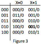
1. Analyze the feedback sequential circuit shown in Figure 1.

2299_Untitled.png

a. Break the feedback loops (Y1, Y2, Y3) and write the next state equations.

b. Construct the transition/output table, showing each of the total stable states. Assume Y3 is high-order (most significant) bit.

c. This circuit has multiple flaws as a fundamental mode circuit. Explain what is wrong with this circuit based upon your results from (b). Be  specific.

d. What needs to change to fix this circuit? Give one or more specific examples.

2. Design a fundamental mode circuit that will continuously cycle with a 3 bit output shown below while the input X=1. The circuit will stop at it's present count when X=0. Thus, the stable states occur only when X=0. The count sequence allows only one bit to change per cycle. The count sequence is 000, 001, 011, 010, 110, 111, 101, 100, 000, etc.

a. Develop the flow table. Assume the state variables Y3, Y2, Y1, with Y3 being the high order bit. Identify the stable states.

b. Determine the reduced switching expressions for the next state equations using K-Maps.

c. Draw the circuit diagram (neatly). Indicate the breakpoints in the feedback loops that correspond to the encoded state table.

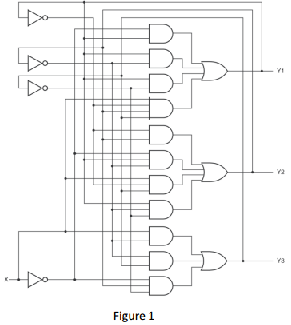
3. A flow table is given in Figure 2 below. Find an assignment of state variables that avoids all critical races. You may add additional states as necessary (using a few state variables as possible).

a. Assign the all-0s combination to state A. Draw an adjacency diagram for the original flow table.

b. Write the modified flow table and another adjacency diagram to support your final state assignment.

1745_figure2.png

4. Create a Verilog simulation model of a 3 bit sequential counter. The current state values (e.g., the flip flop outputs) should reflect the count output. The count sequence for the code is 000, 001, 011, 010, 110, 100, 101, 111. Include a $Monitor print statement that includes your name, ECE class section number and date with approximate time of run. You can modify the Lecture 17 example models for your implementation. Additional design requirements are as follows:

a. Implement a clock with a 10ns clock period with balanced 5ns high and low . The simulation should be positive edge triggered.

b. Follow the example model(s) by including an initial 15ns initialization period.

c. Implement a control input, C, that will stop the count sequence when C=0. The sequence will continue when C=1. Using the C input only, your simulation count should pause for 30 ns after 011 and 100.

d. Create a $Monitor statement to print the value of C, current time and the current count for each 10 ns clock cycle. The simulation should stop when the final count is reached. Show a printout of your console listing AND the wave diagram (showing clock, C, and count signals).

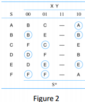
5. Create a Verilog model for the sequence detector state and output table shown in Figure 3. Your test bench should include a verify task that validates the output for the given input at each clock cycle. You can modify the Lecture 17 example models for your implementation. Include a $Monitor statement that prints your name, section number, date and approximate time of model run.

(a). Use the test sequence shown below. This sequence will result in a valid test for each transition in your state table. Show a printout of your console listing that captures the current input, output and expected output for each clock cycle.

(b). Once you have completed a valid run with the test sequence, modify your model to replace next state 001 on row 010 under X=1 with 100. This should cause your test bench to fail and stop the simulation when the error is encountered. Repeat for the same test sequence. Show a printout of your console listing (it should stop due to the break in the state machine).

1131_figure.png

Reference no: EM131005332

Questions Cloud

Find an equation for the indicated plane : For the curve r(t), find an equation for the indicated plane at the given value of t. r(t) = (t2 - 10)i + (2t - 3)j + 9k; osculating plane at t = 0
Find the angle between the velocity and acceleration vectors : The vector r(t) is the position vector of a particle at time t. Find the angle between the velocity and the acceleration vectors at time t = 0. r(t) = (6t2 + 5)i + (2t3 - 8t)k.
Find the sum of the series : Find the sum of the series. Use a graphing utility to find the indicated partial sum and complete the table. (Round your answers to four decimal places.)
Discuss the images of america the european writers : Based on the readings from weeks one and two, discuss the images of America the European writers constructed to promote colonization and settlement. What kinds of unique natural resources and environmental factors did they extol in their accounts ..
Draw an adjacency diagram for the original flow table : A flow table is given in Figure 2 below. Find an assignment of state variables that avoids all critical races. You may add additional states as necessary (using a few state variables as possible). Assign the all-0s combination to state A. Draw an a..
What are the key issues brought about in the conversation : What are the key issues brought about in the conversation? What are the key symptoms and what are the underlying problems? Be specific in your answers
Affects of ocean acidification on ocean plants and animals : Your slides/screens/etc. should also have just the key points of your presentation. The majority of the information should come from your speech. You may either read note cards or present from memory, but do not "read the screen".
Which dissolves much faster in acidic water : Which of these are best able to adopt to increasing acidity of ocean water - Which of these does not have a significant coral reef-based tourism and fishing industry?
Do not want to do anything illegal and unethical : If you do not make this offer to the buyer, you have very good reason to believe that your major competitor will. You do not want to lose this sale, but you also do not want to do anything illegal and/or unethical

Reviews

Write a Review

Electrical Engineering Questions & Answers

  Find what is the current in the resistor at time t

A 10 microFarad capacitor is in series with a 100 ohm resistor, a switch, and a 10.0 volt battery. At time t = 0 seconds the switch is closed. What is the current in the resistor at time t = 0.1 microseconds. What is the current in the resistor at ti..

  Determine the time constants for transient rise and decay

For the Circuit shown below, V1=5V, R1= 20 kiloOhm, R2= 100kiloOhm, and C= 0.1 microF. Assume the switch in the circuit below has been open for a long time. At t=0, the switch is closed and at t=5 sec the switch is re-opened.

  Calculate the voltage across it and the current through it

A series circuit has the following components. For each, calculate the voltage across it and the current through it. Component voltage Current 9 V source 9V 9.1 Kohm resistor 1 Kohm resistor 2.2 kohm resistor.

  Single phase transformer

A 500 kVA single phase transformer with 0.012 p.u. resistance and 0.06 p.u. reactance, is Connected in parallel with a 250 kVA single phase transformer with 0.014 p.u. resistance and 0.045 p.u.

  What is the time required for the capacitor voltage

A capacitor in an RC circuit with R = 5.00 ohm and C = 6.00 mF is being charged. What is the time required for the capacitor voltage to reach 86.5 percent of its steady-state value

  What are the alternative methods of controlling motors

What are the advantages and disadvantages of controlling the Induction motor speed by adjusting the voltage What are the alternative methods

  Write a sop expression for g in sort-hand notation

Given the following function in canonical SOP form, h = a'bc' + a'bc + ab'c + abc' + abc use Boolean algebra to simplify h down to a minimum SOP expression that contain only 2 terms and 3 literals.

  Design the electronic processor that must be connected

The converter canreceive signals from 0 V to 5.0V. Design the electronic processorthat must be connected between the sensor´s output and thecomputer´s converter A/D input; so that maximum sensibility is obtained. Justify each single proposal you m..

  Write down the expression for the frequency-dependent

Write down the expression for the frequency-dependent open-loop gain of an operational amplifier. Sketch the magnitude of the open-loop gain of an operational amplifier as a function of frequency. Explain what is meant by a `single-lag' response o..

  What range of k that makes the impulse response to zero

In the difference equation below K is a real number greater than 0. y[n) = x[n] + Ky[n] A) (2pt)Find the range of values of K that makes the impulse response grow without bound. B)

  Find level of acceptor doping we need to convert the wafer

A n-type Si wafer is doped with Nd=1e15/cm^3, find the level of acceptor doping we need to convert the wafer from n-type to p-type, with a target hole density p=5e15/cm^3. also ni = 1e10/cm^3

  Determine the real power-reactive power and apparent power

A series RC circuit is powered by a voltage supply of 120Vac and60Hz. The resistor has a resistance of 80W and capacitive reactanceis 60W. (1) Sketch a schematic for this circuit (2) Determine the capacitance of the capacitor

Free Assignment Quote

Assured A++ Grade

Get guaranteed satisfaction & time on delivery in every assignment order you paid with us! We ensure premium quality solution document along with free turntin report!

All rights reserved! Copyrights ©2019-2020 ExpertsMind IT Educational Pvt Ltd