Reference no: EM131723576
Assignment: Diode Circuits Lab- Half-Wave and Full-Wave Rectifier
Introduction:
Lab is based on half-wave and full-wave rectifiers. Rectifiers are widely used in power supplies to provide the required DC voltage.
Materials and Equipment: Materials:
• Simulated Parts (Multisim):
o 10:1 center-tapped transformer (refer to tutorial at the end of the lab to access)
o Two diodes 1N4001
o One 2.2 kΩ resistor
o One 100 μF, 50 V electrolytic capacitor
o One fuse (any rating is fine since it is for simulation only). To access the fuse, under Master Database > Group > Power > Fuse
Equipment:
• Virtual Instrument
o Tektronix oscilloscope
• Function Generator (top right of the Multisim screen)
Procedure:
Note: Multisim must be configured so a date and time stamp is visible in all simulations. Omission of the date and time stamp causes the lab to be worth only 1%. Please refer to the procedure to view date and time stamp at the end of the lab.
Part A: Half wave rectification: Software (Multisim):
1. Construct the circuit of a half-wave rectifier in Figure 1 in Multisim. Use a function generator to provide the AC input of 30VRMS at 60 Hz (Make sure to convert the RMS to Peak voltage) and use a center tapped transformer to obtain VSEC. With a 10:1 ratio, the VSEC should be 3 VRMS. Be sure to set the tolerance of the resistor to 10% (refer to the tutorial in Tools and Templates).
2. Connect the Tektronix oscilloscope so that channel 1 is across the secondary output side of the transformer and channel 2 is across the load resistor (RL). Observe the waveforms VSEC and VLOAD.
3. The output isn't very useful as a DC source because of the variations in the output waveform. In order to produce steady DC from a rectified AC output, you need to add a filter. There will be an AC ripple voltage component at the power supply frequency for a half-wave rectifier, twice that for full-wave, where the voltage is not completely smoothed. Connect a 100 μF capacitor (C1) in parallel with the load resistor (RL). (Note the polarity of the capacitor).
4. Measure and plot the peak-to-peak ripple voltage, V8RIPPLE, of the output. Measure the ripple frequency. Tabulate all data gathered and compare the results with and without the filter capacitor.
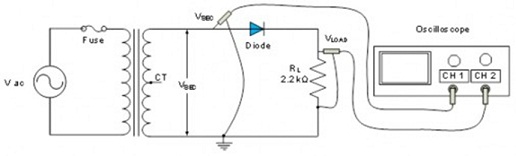
Figure 1
Review questions:
1. What is the purpose of having a half-wave rectifier in the circuit?
2. Describe the procedure in this lab to arrive at the final design of both the hardware portion and the software portion to achieve the design objectives?
3. Discuss the impact of having the capacitor on the output voltage and the effect of additional load on the ripple voltage.
Deliverables:
1. Measured voltage VSEC, the output peak voltage, VLOAD and ripple voltage VRIPPLE. Capture screenshots of your measurements from Multisim.
Part B: Full wave rectification: Software (Multisim):
1. Construct the circuit of a full-wave rectifier in Figure 2 in Multisim. Use a function generator to provide the AC input of 30VRMS at 60 Hz (Make sure to convert the RMS to Peak voltage) and use a center tapped transformer to obtain VSEC. Notice that the ground for the circuit has changed. With a 10:1 ratio, the VSEC should be 3 VRMS. Be sure to set the tolerance of the resistor to 10% (refer to the tutorial in Tools and Templates).
2. Connect the Tektronix oscilloscope so that each channel is across each diode. Observe the waveforms VSEC across each diode and notice that they are out of phase with each other. You can use the third channel to observe the output voltage VLOAD across the resistor.
3. In order to produce steady DC from a rectified AC output, you need to add a filter. Connect a 100 μF capacitor (C1) in parallel with the load resistor (RL). (Note the polarity of the capacitor).
4. Measure the peak-to-peak ripple voltage, VRIPPLE, of the output. Measure the ripple frequency. Tabulate all data gathered and compare the results with and without the filter capacitor.
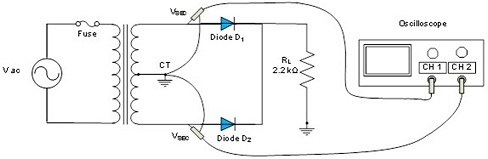
Figure 2
Review questions:
1. What is the purpose of having a full-wave rectifier in the circuit?
2. Describe the procedure in this lab to arrive at the final design of both the hardware portion and the software portion to achieve the design objectives?
3. Discuss the impact of having the capacitor on the output voltage and the effect of additional load on the ripple voltage.
4. How is the output of the full-wave rectifier different from half-wave rectifier?
Assignment - Half-wave and Full-wave Rectifier
Electronics I and Lab
Half-wave and Full-wave Rectifier
1. The half-wave rectifier has a diode in series with a load resistor.
A. True
B. False
2. With a half-wave rectifier, the output frequency equals the input frequency.
A. True
B. False
3. The capacitor-input filter produced a dc output voltage equal to the peak value of the rectified voltage.
A. True
B. False
4. A diode circuit used to protect a sensitive circuit is called a ______.
5. Half-wave rectifier voltage produces__________.
A. bi-directional current flow
B. unidirectional current flow
C. no current flow
D. alternating current
6. What is the term for a special kind of high frequency power supply used in computers and monitors?
A. crowbar protection
B. half-wave
C. bridge
D. switching regulator
7. The voltage that must be less than the breakdown voltage of the diode in order to prevent damage to the diode is the ________.
A. peak inverse voltage
B. maximum diode voltage
C. reverse surge voltage
D. maximum peak voltage
8. Assume the input signal to a rectifier circuit has a peak value of Vm = 12 V and is at a frequency of 60 Hz. Assume the output load resistance is R = 2kΩ and the ripple voltage is to be limited to Vr= 0.4 V. Determine the capacitance required to yield this specification for a (a) full-wave rectifier and (b) half-wave rectifier. Show all work.
9. A full-wave rectifier is to be designed to produce a peak output voltage of 12 V, deliver 120 mA to the load, and produce an output with a ripple of not more than 5 percent. An input line voltage of 120 V (rms), 60 Hz is available. Consider a bridge type rectifier. Specify the transformer ratio and the size of the required filter capacitor. Show all work.
10. Silicon diodes are used in a two-diode full-wave rectifier circuit to supply a load with 12 volts D.C. Assuming ideal diodes and that the load resistance is 12 ohms, compute the secondary transformer voltage, the load ripple voltage, and the efficiency of the rectifier. Show all work.
11. A half-wave rectifier using silicon diode has a secondary emf of 14.14 V (rms) with a resistance of 0.2 Ω. The diode has a forward resistance of 0.05 Ω and a threshold voltage of 0.7 V. If load resistance is 10 Ω, determine the following:
o dc load current
o dc load voltage
o voltage regulation
o circuit efficiency
o diode PIV and current rating.
Attachment:- Lab-Report-Template.rar