Circuit used to create an edge-triggered d flip-flop

Assignment Help Other Engineering
Reference no: EM131081293

OBJECTIVES

1.      To simulate the operation of a circuit used to create an edge-triggered D flip-flop.

2.      To test the operation of a 74LS74 D flip-flop and compare the operation with the predicted behavior.

3.      To describe and simulate the operation of edge-triggered D-type and J-K flip-flops using VHDL.

4.      To test the operation of a 74LS112 J-K flip-flop and compare the operation with the predicted behavior.

PARTS LIST

Quartus II Design Software-Version 9.1

Frequency Generator

Oscilloscope

Parts:

      1-Red LED              1 - Green LED
      1-74LS112 dual J-K flip-flop                      1-1.0 kΩ resistor, ¼ W                                 2-330 Ω resistors, ¼ W                                  1-SPDT Switch, DIP configuration

INTRODUCTION

Edge-triggered devices react only on a signal transition, either low-to-high (rising edge) or high-to-low (falling edge). This allows for the development of logic circuits in which the action of the components only occurs at a specified point in time. These circuits generally use a common signal, called a clock, as the trigger. These circuits are called synchronous.

Flip-flops can have two different types of inputs. Inputs that are used on clock transitions are called synchronous inputs; inputs that cause a change in the output independent of the clock are called asynchronous.

Synchronous inputs must be stable for some time before a clock transition to ensure the flip-flop will properly react. If the synchronous input changes too close to the clock transition, the flip-flop may miss or misinterpret the input. The time required for the input to precede the clock transition is called the set-up time.

Many of the VHDL features required for the description of sequential (clocked) circuits are covered in the Lecture Notes. The use of the PROCESSfunction allows for the step-by-step evaluation of a circuit and the ability to model clocked designs.The function needed to model the action of clocked circuits is called EVENT. The EVENT function can be combined with other operators to create an attribute. By combining an apostrophe with EVENT, the attribute 'EVENT is created.  The 'EVENT attribute can be added to a signal to create acondition to detect a clock transition.

The 'EVENT attribute can only be used within a process.The commandclock'EVENT indicates, when true, that a transition has occurred on the input called clock. With the use of an IF operator, this can be used to indicate a clock edge. The statement IF (clock'EVENT AND clock = '1') will be true only on the rising edge of the clock.  A falling edge trigger would occur for the statement IF (clock 'EVENT AND clock = '0').

As an example of a clocked circuit, consider the D flip-flop show in Figure 4.1and the VHDL file in Figure 4.2.
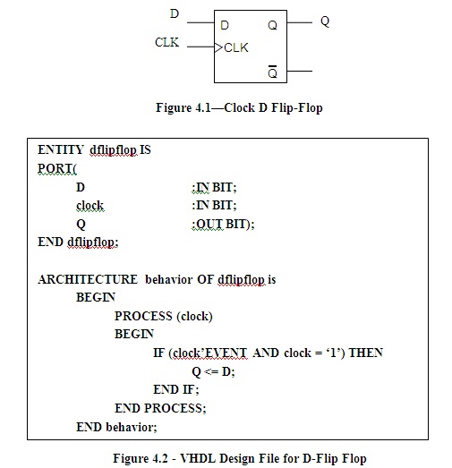
311_ku.jpg

ENTITY dflipflop IS

            PORT(

                        D                                 :IN BIT;

                        clock                           :IN BIT;

                        Q                                 :OUT BIT);

            END dflipflop;

ARCHITECTURE behavior OF dflipflop is

            BEGIN

                        PROCESS (clock)
                        BEGIN
                                    IF (clock'EVENT AND clock = '1') THEN
                                                Q <= D;
                                    END IF;

                        END PROCESS;

            END behavior;

Figure 4.2 - VHDL Design File for D-Flip Flop

In this example, the statements within the IF portion are evaluated when there is a change in clock from a 0 to a 1 state. Until this change is detected the value of Q remains unchanged.

Asanother example of modeling,consider the 74LS74 D flip-flop, Figure 4.3, with the addition of an asynchronous clear and preset function. The code is given in Figure 4.4.

410_ku.jpg

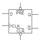
Figure 4.3-74LS74 D Flip-Flop

ENTITY dflipflop IS

            PORT(

                        D, PRE, CLR                                    :IN BIT;

                        CLOCK                                 :IN BIT;

                        Q,QN                                      :BUFFER BIT);

            END dflipflop;

            ARCHITECTURE behavior OF dflipflop is

            BEGIN

PROCESS (CLOCK, CLR, PRE)
            BEGIN
                        IF CLR = '0' THEN

                                    Q <= '0'; QN <= '1';

                        ELSIF PRE = '0' THEN

                                    Q <= '1'; QN <= '0';             

ELSIF (clock'EVENT AND clock = '1') THEN
                        Q <= D;  QN <= NOT D;
 END IF;

                        END PROCESS;

            END behavior;

Figure 4.4 - VHDL File for the 74LS74 D Flip-Flop

PROCEDURE

A. VHDL Entry and Simulation of the 74LS74 D Flip-Flop

1.      Open Quartus II and create a new project nameddflipflop.

2.      Enter, compile, and save the file for the 74LS74 D flip-flop shown in Figure 4.4.

3.      Open the Vector Waveform window with an end time of 1.0 ms and grid size of 50 ns.

4.      Create a simulation that sets up the following.

  1. Set D for a period of 100 ns.
  2. Set CLOCK for a period of 50 ns.
  1. Set PRE = 1 for 0 to 450 ns and 600 ns to 1ms.
  1. Set CLR = 1 for 150 ns to 850 ns.

5.      Run the simulator. Print out a hardcopy. Turn this in with your report.

B.  VHDL Entry and Simulation of the 74LS112 J-K Flip-Flop

1.  A schematic for the 74LS112 J-K flip-flop is shown in Figure 4.5and a partial text file is in Figure 4.6. Complete this file, compile, and save the design as jkflipflop.

1963_ku.jpg

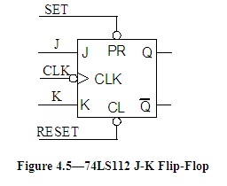
ENTITY jkflipflop IS

            PORT(

                        J, K, PRE, CLR, CLOCK   :IN BIT;

                        Q,QN                                      :OUT BIT);

            END jkflipflop;

            ARCHITECTURE behavior OF jkflipflop is

            BEGIN

PROCESS (CLOCK, CLR, PRE)
            BEGIN
                        IF CLR = '0' THEN

                                    Q <= '0'; QN <= '1';

                        ELSIF PRE = '0' THEN

                                                            Q <= '1'; QN <= '0'; 

                                                ELSIF                                           

END IF;

                        END PROCESS;

            END behavior;

Figure 4.6-Partial VHDL Description of 74LS112 J-K Flip-Flop

2.      Print out a copy of the completed Design File and turn it in with your report.

3.      Open the Waveform Vector window with the same end time and grid as before.

4.      Create a simulation that sets up the following.

  1. Set J for a period of 75nS.
  1. Set K for a period of 125nS
  1. Set CLOCK for a period of 50nS.
  1. Set PRE = 1 for 0 to 450nS and 600nS to 1mS.
  1. Set CLR = 1 for 150nS to 850nS.

5.      Run the simulation and print out a hardcopy. Turn this in with your report.

6.      Using the simulation results, complete the truth table below.

PRE

CLR

J

K

CLOCK

Q

Q_NOT

1

0


0

1


1

1

0

0


1

1

0

1


1

1

1

0


1

1

1

1


74LS112 J-K Flip-Flop Truth Table

7.      From the simulation result, determine the values for propagation times for the Q output from the active clock edge. Record these values below.

tPHL = ______________________       tPLH = ________________________

C. Test the74LS112 J-K Flip-Flop

1.      Build the J-K flip-flop circuit shown in Figure 4.7. Remember to attach VCC to pin 16 and ground to pin 8.

Figure 4.7-74LS112 J-K Flip-Flop Test Circuit

2.      Using the circuit, verify that the operation follows the truth table from the simulation.

3.      Increase the pulse generator output to 100 kHz. Set the switches so that all of the flip-flop inputs are high and remove the LEDs and resistors. Using the oscilloscope, measure the propagation times for the Q output from the active clock edge. Record the value below.

tPHL = ______________________       tPLH = ________________________

Reference no: EM131081293

Questions Cloud

Ee computation electromagnetic : The project is supposed to be a small research project, so it should be done such that you can show me and the class you have put in good effort and have been creative and thoughtful about it. As far as page limit goes, there is really no hard lim..
Mission of maximizing shareholder value : With the mission of maximizing shareholder value in mind, how could the health care financial Manager help to motivate a large group of employees to exceptional performance? Explain in detail.
Compute free cash flow that relies : Construct a spreadsheet model to compute free cash flow that relies on the following assumptions or estimates: What level of annual unit sales does it take for the investment to achieve a zero NPV? Use your spreadsheet model to answer this question...
Explain why this is the underlying problem : Explain how a clearly defined problem could help with solutions.
Circuit used to create an edge-triggered d flip-flop : To simulate the operation of a circuit used to create an edge-triggered D flip-flop. To test the operation of a 74LS74 D flip-flop and compare the operation with the predicted behavior.
Potential multinational corporation : Describe the risks that a potential multinational corporation may no longer face as it ceases to be a domestic corporation. Discuss total and unique risks for a potential multinational corporation.
What should a criminal defense lawyer do when the lawyer : According to Rich Deem, "We are instructed not to lie, and lying is strongly condemned"(n.page). Destroying evidence to prove guilt is lying and that is unacceptable and prosecutors and defense attorneys should follow the proper vertical and horiz..
Month forward premium-discount using european term : (a) Is Swiss Franc trading at premium or discount vs. USD in the forward market? (b) Calculate the 1-month forward premium/discount using European Term (30 days).
Percent coupon bond : What is the equation for the following question Compute the price of a 3.8 percent coupon bond with 18 years left to maturity and a market interest rate of 6.8 percent.

Reviews

Write a Review

Other Engineering Questions & Answers

  Assume that you are managing a design project which will

imagine you are managing a design project that will create an interface for automobile mechanics. the interface would

  Explain why a trickling filter is used in the plant

Write a one-page memo that explains what you saw and the reasons behind some of the processes that were conducted within the plant. For example, if you saw trickling filters, explain why a trickling filter is used in the plant.

  Determining the complementary error function

Suppose that the signaling rate doubled. Find the new value of the average probability of error. You may use Table to evaluate the complementary error function.

  Constant pressure expansion determine

Problem 1: 10 moles of an ideal gas with Cp = 32J/mol.K expands abiabatically from 340K and 5 atm to a final state where its volume doubles. For a constant pressure expansion determine

  Pseudoplastic and a newtonian fluid please

A Bingham plastic, a dilatant, a pseudoplastic and a Newtonian fluid Please?

  Developing a work breakdown structure

My project is a cutter that cuts a seat belt after a crash when the car comes to a complete stop and it is right side up if the car is upside down then when the emergency crew gets there and release the pressure of the person hanging it would then..

  Draw the free-body diagram of the bar

Draw the free-body diagram of the bar, which has a negligible thickness and smooth points of contact at A, B, and C. Explain the significance of each force on the diagram. (See Fig)

  How many fuel bundles are needed for a boiling water reactor

Calculate how many fuel bundles are needed for a Boiling Water Reactor (BWR) core for 2 years fuel cycle

  Specify predecessor-successor linkages between two tasks

What is another way to specify predecessor-successor linkages between two tasks? Describe AND provide a screen shot of the steps

  What is maximum recoil distance

A 1 KN shell is forced from a gun weighting 150 KN with a nozzle velocity of 500 m/sec. If the recoil velocity of the gun is checked by a set of springs having modulus 500 KN/m. What is maximum recoil distance?

  Impact of the chosen energy source on society

Impact of the chosen energy source on society - impact of engineering work, related to the type of energy source chosen, on the environment

  What the advantages of digital signals over analog signals

What are the advantages of digital signals over analog signals? Cover noise suppression in your explanation

Free Assignment Quote

Assured A++ Grade

Get guaranteed satisfaction & time on delivery in every assignment order you paid with us! We ensure premium quality solution document along with free turntin report!

All rights reserved! Copyrights ©2019-2020 ExpertsMind IT Educational Pvt Ltd