Reference no: EM133556199
Design for Shear and Flexure
Note: For all problems provide neat drawings and show clearly all calculations. Make any assumptions needed.
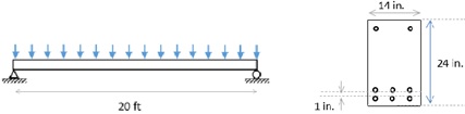
Question 1. The beam shown in the figure has been designed for flexure for a factored uniform load of 10 kips/ft. The concrete strength is 4,500 psi and the steel reinforcement includes is 8 #5 Grade 60 bars as shown in the drawing. In your calculations assume cover of 1 inch is used.
a. Estimate pb and pt-c, for positive flexure. Hint: ignore the compression reinforcement.
b. Assess the design for flexure and explain if it is a good or a bad design. If it is not a good design, redesign the beam for flexure.
c. For the design given, calculate the nominal shear strength of the beam section using ACI 318 for Vc, and design the shear reinforcement for three case: i) unreduced shear force and uniform tie spacing, ii) reduced shear force and uniform tie spacing, iii) reduced shear force and nonuniform tie spacing.
Question 2. A simply supported rectangular beam with a length of span of 32 ft carries its self-weight, an additional dead load of 2.4 kips/ft, and a live load of 1.5 kips/ft. The beam has a width of 12 in., height of 18 in., clear cover for the longitudinal reinforcement of 15 in., and it is constructed with concrete with compressive strength of 3,500 psi and four No. 5 Grade 60 steel bars on the tension side. Considering two loading scenarios, 1.4DL and 1.2 DL+1.6LL,
- Estimate Ρ0 and Ρt-c,: for positive flexure, and assess the flexural design of the beam, as you did in Problem 1. There is no need to redesign this beam.
- Then, design the shear reinforcement in the beam for the: unreduced shear demand, using uniform reinforcement, reduced shear demand, using uniform reinforcement, reduced shear demand and non-uniform spacing. Use the minimum number of stirrups required by specifying two or three areas with different spacing along the half-beam and one area without ties where allowed by ACI.
Question 3. Assume a beam with stirrups inclined at 60° angle with respect to the longitudinal steel resisting cracks developing at 45° angles. Derive analytically the equation that allows you to calculate the shear resistance provided by the stirrups as a function of the stirrup and crack angle.