Reference no: EM132369730
Pasture Road Project - Assignment Brief
Introduction and Background
Bordertown is a rural town servicing a diverse and vibrant farming and grazing industry. The main agricultural supply, produce / livestock distribution and industrial areas are located on the northern side of town. The majority of heavy vehicle traffic travels to and from the north-west and accesses Bordertown via the Main Highway. Unfortunately this means that heavy vehicles, including B-double trucks, are required to pass through the centre of town (CBD) causing traffic congestion and safety issues.
There is an alternate route via Pasture and North roads. However, Pasture Road is currently narrow, mostly single lane seal and posted at 60km/h - it is not a desirable route particularly for heavy vehicles. Refer Figure 1-1.
The road authority now wishes to upgrade Pasture Road to make it a viable alternate route, particularly for heavy Commercial Vehicles (CVs). Pasture Road is currently 19m Semi general access only, however it is to be upgraded to a B-Double route.
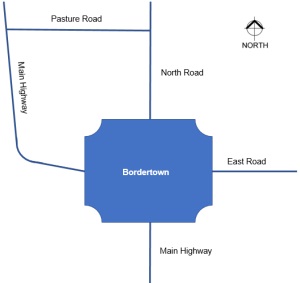
Figure 1-1 Location Diagram
2.0 Project Site
Pasture Road is in a rural environment. Terrain is mostly open and flat to mildly undulating. Land use adjacent to the road in the vicinity of project site is predominantly pastural / grazing.
Pasture Road has been split into 3 sections (refer Figure 1-2) and is to be designed and constructed as funding becomes available.
• Section 1 (≈5km) to be designed by others (not part of this project)
• Section 2 (≈2.7km) being designed by your team (this project/assignment)
• Section 3 (≈3.8km) to be designed by others (not part of this project)
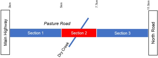
Figure 1-2 Sections
3.0 Existing Road (Pasture Road)
With reference to Figure 1-2.
Section 1
• Approximately 5 km long and reasonably straight. There are several short length horizontal curves ranging 700 to 750m in radius.
• This section is single lane seal with gravel shoulders.
• Terrain is mildly undulating.
• Future upgrade:
o Will mostly keep the existing alignment,
o Cross section will be based on that developed for Section 2.
Section 2
• Approximately 2.7 km long and has three horizontal curves ranging 325 to 450m in radius.
• Existing cross section (variable):
o 7.6m carriageway
» 2x 2.8m sealed traffic lanes
» 2x 1.0m unsealed shoulders
o Crossfall is 2-4%
o Batters (cut, fill and table drain) are generally 3:1 but sometimes 2:1
o Table drains are V-drains
Section 3
• Approximately 4.2 km long and is generally straight. There are two horizontal curves, R500 and R680 respectively.
• This section is single lane seal with gravel shoulders.
• Terrain is reasonably flat
• Future upgrade:
o Will mostly keep the existing alignment,
o Cross section will be based on that developed for Section 2.
4.0 Traffic Prediction
Current traffic along Pasture Road is very low and largely consists of local farming traffic with occasional livestock semi-trailers.
For the purposes of design, the road authority commissioned a traffic modelling study (including an origin-destination survey) to predict the expected traffic volume and composition at opening of the upgraded road once fully upgraded (all three sections).
The findings of the modelling are:
• AADT: 730 vehicles
• Percentage of commercial vehicles (%CVs) = 30%
• Growth rate for traffic (from year opening onwards) will be 2.2 - 3.5% Pasture Road will be sign posted as the primary route for CVs accessing Bordertown.
5.0 Design Requirements
The following design requirements and intentions have been set by the road authority.
• Design guideline - Guide to Road Design by Austroads (AGRD).
• Following existing alignment is preferable, however it is expected that some realignment will be required in the vicinity of Dry Creek (which is within Section 2) to facilitate the construction of a new replacement structure.
• Maximum superelevation to be used is 6%.
• Pasture Road is not considered a bus or cycling route.
• Posted speed of road to be increased to 90km/hr.
• Design life = 30 years.
• Traffic:
• AADT growth rate 3% per year (compound growth).
• Design Vehicle to be B-Double.
• Drainage:
• Dry Creek Bridge (timber):
o Currently floods (overtops) and is to be replaced with a large box culvert structure to improve flood immunity - flood water is not to inundate the traffic lanes for design flood (AEP 2%).
o The replacement culvert has been designed by hydraulic specialists - it is to be 4/2400mm x 2400mm RCBC.
• Existing table drains show signs of scour. Erosion needs to be mitigated.
• Intersections:
• Traffic analysis warrants basic intersection layouts for left and right turns into minor roads.
• Intersection safety is an important consideration.
6.0 Road Design Project Tasks (Assignment 1)
Scope of Assignment Work
You are required to work in teams of 4. Approach is collective and collaborative learning. Tasks should be equally divided amongst team members.
Work should be aligned with the material presented during lectures. Sections of AGRD not referenced during lectures do not need to be used.
Tasks
Your team is assisting the preliminary or feasibility design (based on information provided in Sections 1 to 5 above) of the project:
• A series of tasks aligned to lecture material will be issued (generally on a weekly basis). The outcome of these tasks is to be reported in your Design Report (refer Section 6.3).
o Some of the tasks will be design based where your team is to propose a design solution for consideration.
o Other tasks will be to review work by others and to either verify if proposal is satisfactory or, suggest changes / improvements.
• Reporting in Design Report is to include your thinking / rationale for proposal. You also need to explain / justify selection of relevant criteria.
This project is informed by:
• The Guide to Road Design (AGRD) and Guide to Traffic Management
(AGTM) by Austroads.
Furthermore:
• Pavement design is not part of this assignment / not to be included.
• Private accesses are not part of this project.
Deliverables
Consistent with this brief your team shall specifically deliver for Assignment 1, the following:
1. Design Report (8 pages of main body text (Sections 1 to 9)) must be completed using the provided template. Any work presented beyond page 8 will not contribute to overall mark. Changes to structure of report will be penalised in marking of assignment.
• Target audience for report are experienced road design engineers.
• Appendices are additional material to main body of report and must contain appropriate detail, calculations and drawings sufficient to inform report audience and support your findings. Appendices must be correctly referenced from within the body of the report. If they are not referenced, they will not be considered in the marking of assignment.
2. Minimum formatting for report: text no less than 11pts, paragraph spacing no less than - Before = 0pts / After = 6pts and Line spacing no less than 14pts.
7.0 Timing
Lectures will be progressively delivered covering material essential for undertaking and completing the assignment:
• Assignment 1: Is due to be submitted by 11:59pm, Friday 13 September 2019.
Relationship of this Project to Unit EGH472
This project aligns with unit learning outcomes:
1. Application of theoretical knowledge, design methodologies, and codes of practice correctly in the design (review) of a road.
2. Use of informational sciences to investigate, analyse and synthesise the civil engineering systems in place along a corridor for which a road is to be designed.
3. Awareness of the social and economic contexts and sustainable engineering practice in the design of a road.
4. Correct written literacy and appropriate collaborative strategies in the preparation of road design submission.
The project, to be completed in teams of four contributing equally, will be the design of key element a segment of road in a rural setting. The purpose of the facilitated design is to give you up-to-date exposure to near real-life road infrastructure projects and to encourage you to discuss the methods and steps of the design process with your peers (i.e. your team).
It is important to point out that the project is a simulated one, and as such, does not correspond directly with the extent of work required, timelines, or organisational arrangements of a real project. Rather, it extracts certain key exercises that would be carried out by the various actors within the road design process.
Assignment Task 1
1. Key information
The Assignment Brief provides all relevant information and guidance with respect to the intentions / requirements of the client (road authority).
Tasks set within this document provide additional guidance and information (details) to complete required work for submission as Assignment 1.
2. Linkage between Lectures and Assignment
Lectures completed and related to tasks:
• L1 - Design Approach and Speed
• L2 - Cross Section Design and Safety Related Design Report sections:
• 1 - Introduction
• 2 - Design traffic
• 3 - Design Speed
• 4 - Type Cross Section
3. Tasks
Commence authoring Section 1 of Design Report.
• All information has been provided however you can continue to refine this section over next few weeks.
Commence and complete authoring of Section 2 of Design Report.
• All information has been provided. It is essential to complete this section as it informs your design tasks.
Commence and complete authoring of Section 3 of Design Report.
• All information has been provided. Careful assessment and consideration is required. It is essential to complete this section as it informs your design tasks.
Commence and complete authoring of Section 4 of Design Report.
• All information has been provided. You are required to develop / design the type cross section (or sections) for the project. For the report, it is suggested to present the elements of the type cross section(s) in tabulated form. You are also required to produce a drawn version of your designed type cross section(s). Table and rationale should be within main body of report, but drawings should be placed in an appendix.
Assignment Task 2
1. Key information
The Assignment Brief provides all relevant information and guidance with respect to the intentions / requirements of the client (road authority).
Tasks set within this document provide additional guidance and information (details) to complete required work for submission as Assignment 1.
2. Linkage between Lectures and Assignment
Lectures completed and related to tasks:
• L3 - Horizontal
Related Design Report sections:
• 6.1 - Horizontal Alignment.
3. Tasks
3.1. Commence and complete authoring of Section 6.1 of Design Report.
• All information has been provided.
• You are required to fully design the first curve currently shown/proposed as R325 (refer Appendix 1). This radius approximately matches the existing curve and it is desired to keep this radius as it maximises the use of existing asset. However you are able to decrease/increase the radius of curve.
• Refer Appendix 2 for geometric detail of example curves at this location.
• You are required to fully design the combined second and third curves currently shown/proposed as R450 reverse curves (refer Appendix 3). You are able to decrease/increase the radius of curve.
• Refer Appendix 4 for geometric detail of example curves at this location.
• Dry Creek crosses new alignment, between the above reverse curves, at approximately Ch1480 (refer Appendix 3).
• Larger drawings / diagrams, such as superelevation diagrams, should be placed in an appendix.
Assignment Task 3
1. Key information
The Assignment Brief provides all relevant information and guidance with respect to the intentions / requirements of the client (road authority).
Tasks set within this document provide additional guidance and information (details) to complete required work for submission as Assignment 1.
2. Linkage between Lectures and Assignment
Lectures completed and related to tasks:
• L4 - Sight Distance and Vertical Alignment Related Design Report sections:
• 5 - Sight Distance
• 6.2 - Vertical Alignment.
3. Tasks
Commence and complete authoring of Section 5 of Design Report.
• All information has been provided.
• Using your design speed, calculate the minimum Stopping Sight Distance to be used for this project in these situations:
o flat
o 6.50% downhill
o 4.25% uphill.
• Calculate the curve perception sight distance (if required) to be used to assess the following possible horizontal curve radii for the project:
o R350 ; transitioned, Lp = 60m
o R500 ; un-transitioned, use 80m of arc
Commence and complete authoring of Section 6.2 of Design Report.
• All information has been provided.
• Using your design speed, calculate the minimum Crest and Sag vertical curves to be used for this project.
Assignment Task 4
1. Key information
The Assignment Brief provides all relevant information and guidance with respect to the intentions / requirements of the client (road authority).
Tasks set within this document provide additional guidance and information (details) to complete required work for submission as Assignment 1.
2. Linkage between Lectures and Assignment
Lectures completed and related to tasks:
• L5 - Alignment Coordination Related Design Report sections:
• 6.3 - Alignment Coordination.
3. Tasks
3.1. Commence and complete authoring of Section 6.3 of Design Report.
• All information has been provided.
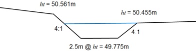
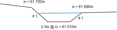
• Assess the four attached drawings for alignment coordination.
• Determine if the coordination is acceptable or not and provide a brief commentary within the report on each drawing.
• If you identify any issues, provide a suggested improvement.
Assignment Task 5
1. Key information
The Assignment Brief provides all relevant information and guidance with respect to the intentions / requirements of the client (road authority).
Tasks set within this document provide additional guidance and information (details) to complete required work for submission as Assignment 1.
2. Linkage between Lectures and Assignment
Lectures completed and related to tasks:
• L6 - Drainage & Intersections Related Design Report sections:
• 7 - Road Drainage
• 8 - Intersections
• 9 - Conclusions and Recommendations
3. Tasks - Drainage
Commence and complete authoring of Section 7 of Design Report.
• All information has been provided.
Table Drain Assessment
Between Chainages 35 - 400 there will be a table drain. Check the capacity of the drain and velocity of flow and assess if design is satisfactory or not?
Table drain geometry @ Ch. 35:
• Average grade of road over length of table drain = 4.1%
• Maximum permissible velocity is 2.0m/s
• Hydrology calculates the inflow to drain as 0.065m3/s per 10m (of table drain)
• If not suitable, suggest how to improve.
Between Chainages 1850 - 2050 there will be a table drain. Check the capacity of the drain and velocity of flow and assess if design is satisfactory or not?
Table drain geometry @ Ch. 1850:
• Average grade of road over length of table drain = 5.5%
• Manning's is slightly better, n = 0.04
• Maximum permissible velocity is 2.0m/s
• Hydrology calculates the inflow to drain as 0.065m3/s per 10m (of table drain)
• If not suitable, suggest how to improve.
Bridge Replacement Culvert Assessment
The 4/2400x2400RCBC culvert as shown in Appendix 1 (2 drawings) has been designed by others. Undertake a simple assessment of the design (identify any adverse issues) and provide comment on suitability.
4. Tasks - Intersections
4.1. Commence and complete authoring of Section 8 of Design Report.
• All information has been provided.
• Calculate the required SISD for the 3 intersections drawings in Appendix 2.
• Assess the intersections for location suitably:
o Assessment to be based on original design as provided; not modifications you may have made to the alignment.
o You will need to consider the vertical alignment as previously supplied.
o There are no trees, buildings or other objects located close to the road that would impede visibility.
• If you identify any issues, provide a suggested improvement.
5. Tasks - Finalise
Commence and complete authoring of Section 9 of Design Report.
Design Report finalisation.
• Review and finalise / complete all sections of report.
• Submit report by due date.
Attachment:- Pasture Road Project.rar