1. Introduction:
Theory: Phase angle is defined as the number of degrees separating two sine waves of the same frequency. The Phase shift is defined as any change that occurs in the phase of one quantity, or in the phase difference between two or more quantities.
For infinitely long sinusoids, a change in Θ is the same as a shift in time, such as a time-delay. If x (t) is delayed (time-shifted) by 1/4 of its cycle, it becomes:
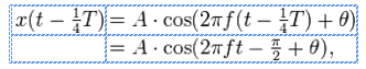
whose "phase" is now Θ- (Π / 2) It has been shifted by (Π / 2) radians.
Material Required: Oscilloscope, frequency generator, connecting wires, resistor, capacitor, potentiometer, multimeter.
Description and Aim: To measure phase angle by using an oscilloscope. The phase angle between two waveforms is calculated by ensuring that they are of same frequency. The amplitude can differ for both these waveforms. An input waveform will be passed through circuit which may make some changes in the phase of this waveform. Hence, the phase angle between the input and output waveforms is measured using the oscilloscope where one channel displays the reference waveform and other channel displays the second signal.
2. Method:
Step 1) First, make a circuit using a capacitor and a resistor. The potentiometer can also be used and turn it fully otherwise. The capacitor creates a phase shift in the waveform passing through it.
Step 2) Connect generator to phase angle circuit block. Using an oscilloscope, set generator for a sine wave output 6Vpk-pk at 1000 Hz.
Step 3) Connect channel 1 probe to input of the generator and channel 2 probe to output across C1. Ensure that oscilloscope trigger source control is set to channel 1. Switch from the vertical mode to ALT. Set ground references of both the channel to the graticule line. The phase angle between channel 1 and channel 2 is approximately zero at this moment.
Step 4) Slowly turn the potentiometer R2 completely clockwise. It makes the phase shift to right direction.
Step 5) Switch vertical mode to channel 1 and adjust time base and variable time base controls on oscilloscope so that one cycle of waveform is having exactly 8 divisions.
Step 6) Calculate phase angle between the two waveforms.
3. Results:
Frequency of waveform = 1000 Hz
V(pk-pk) = 6V
No of horizontal divisions for one cycle of waveforms = 8
Measure of one division = 45°
Phase angle = 8 X 45° / 5 = 360° / 5 = 72°
(how did u get 5 in above line...mention that here)
4. Discussion:
Phase measurement of a waveform using oscilloscope is done. Prime source of error is resolution error, which is reduced by ensuring phase crossings align with ticks of oscilloscope. If this experiment needs to be repeated for higher frequencies time step has to be properly changed to avoid quantization error.