Create and simulate a network similar to the one shown here, using the NetML system.
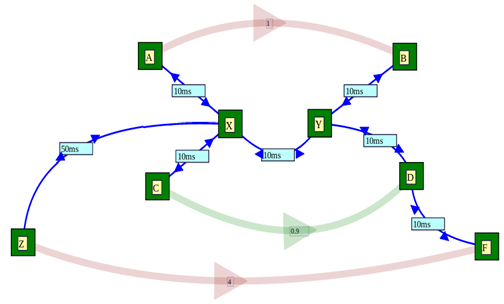
The network is a little more complex, as depicted at the right. There is an extra node which is a lot further away. In the diagram at the right, the labels indicate the propagation delay of each link.
The issue we wish to explore in this assignment is whether a traffic flow can be disadvantaged by passing along a path with larger propagation delay than the other flows which share the network.
In addition, we would like to explore ways in which this performance problem (if it exists) might be alleviated. The methods we wish to explore as follows:
- replace the default DropTail queue at the congested node, X, by a RED queue;
- change the parameters of the DropTail queue: in particular, doubling the buffer capacity or halving the buffer capacity;
- change the parameters of the RED queue: in particular, selecting different values for linterm, minTh, maxTh and gentle;
- try different values of the propagation delay from Z to X starting at 50ms and going up to 500ms, to see if the problem becomes more serious with delay (and less serious as the delay differential decreases);
- check if the problem is different depending on which of the two flows (the one with a long delay and the one with a short delay) starts first.
Network Setup
All the links in the network should have a data rate of 10 Mbps and a propagation delay of 10 ms except the link from X to Y, which should have a data rate of 2 Mbps, and the link from Z to X, which should have a propagation delay of 50ms initially, and then varying up to 500 ms.
The top and bottom traffic flows should be ftp transfers of 10,000,000 bytes each. The one at the top should start at 1s, and the one below at 4s (although this will be varied during the experiments). Both flows should have a finish time of 10s and the PacketSize parameter of both should be 1000. The other traffic stream should be a UDP Ping flow, with an Interval of 0.01, starting at time 0.9s, and finishing at time 10 and with many packets: 100,000.
Criteria
- A satisfactory assignment document has been prepared, a network has been created and is depicted in a diagram in the assignment document.
- Graphs which explain the behaviour of the network in its original setup are presented including dropped packets, the congestion window between A and B and between Z and F, and throughput of these two flows.
- A description of the normal behaviour of the network is included in the assignment document. This should include a comparison of the throughput of the flow with a long delay to the flow with a short delay.
- A description of the behaviour of the network when the DropTail queue is replaced by a RED queue is provided. This should include plots of key performance indicators such as throughput for both FTP flows.
- Experiments have been conducted to determine the effect of the delay difference, between the two flows, on the different performance each flow experiences.
- Experiments have been conducted to determine the effect on performance for the F to Z flow of changes in the buffer size of the DropTail queue at X.
- Experiments have been conducted to determine the effect on the performance of the F to Z flow of changes in the RED queue parameters.
- Experiments have been conducted to show if it makes a difference if the flow from A to B starts before or after the flow from Z to F.
- The assignment includes a discussion section in which the issue of fair access to network resources by flows with different path lengths is discussed.