Calculation of receiving end voltage, Electrical Engineering

Assignment Help:

Calculation of Receiving End Voltage

Consider the simple circuit shown in Figure.

333_Calculation of Receiving End Voltage.png

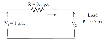
To find the voltage V2 using analytical method:

  P = I V2 = 0.5      ..... (1)

 V2 = V1 - R I      ..... (2)

 V2 = 1 - 0.1 I

∴  0.5 = I ( 1 - 0.1 I ) = I - 0.1 I2 

or I2 - 10 I + 5 = 0        ..... (3)

So I = 10 + √ 100 -20 / 2 = 10 + 8.944272 / 2 = 0.527864 or 9.472 p.u.

∴ V2 = 1 - 0.1 × 0.527864 = 0.9472136 p.u.

Using   I = 9.472 p.u.   gives an unacceptable solution.

Using iterative method, V2 may be found as:

(i) Assume V2 (call it 1V2)

(ii) Find I = P / V2

(iii) Find ?V = R I

(iv) Find new value of V2 = V1 - R I ( call it 2V2)

(v) Check |2 V2 - 1V2|

Solving the previous example by the iterative method gives:

2133_Calculation of Receiving End Voltage 2.png

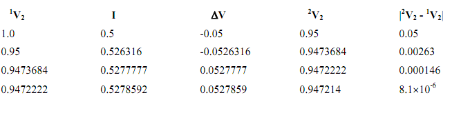
Notice the improvement in the new value of V2 and the absolute error |2V2 - 1V2|. The calculation may be terminated at the end of any iteration depending on the required accuracy |2V2 - 1V2|.


Related Discussions:- Calculation of receiving end voltage

Newton''s laws of motion in terms of particle motion, 1. Sum of forces is z...

1. Sum of forces is zero velocity remains constant.[If the particle is initially at rest, it will remain at rest for as long as the sum of the forces is zero]. 2. Sum F of for

When mt2 is negative and g is positive , When MT 2 is Negative  and g is ...

When MT 2 is Negative  and g is positive In this  case  gate  current  flows  through  junctions P 2 N 2   electrons  are injected from  N 2   layer to  P 2   a result  junct

Describing the steady state effect , Select the response describing the ste...

Select the response describing the steady state effect of increasing the air gap for otherwise identical devices, one operating with constant DC voltage excitation and one with con

Discuss the low- and high-frequency designs, Consider a CS JFET amplifier w...

Consider a CS JFET amplifier with the following parameters : R 1 = 350 k; R 2 = 100 k, R SS = 1200 , R D = 900 , R L = 1000 , R S = 2000 , ro = 15 k,gm = 6 × 10 -3 S,

Biomedical question, Find the rms voltage of the given cardiac wave

Find the rms voltage of the given cardiac wave

500Mhz Collpitts Oscillator, How to design an Oscillator Circuit (500 MHz r...

How to design an Oscillator Circuit (500 MHz range) with no Op amps?

Determine the peak fundamental component of the mmf, Q. A two-pole, three-p...

Q. A two-pole, three-phase synchronous generator has a balanced three-phase winding with 15 turns per phase. If the three-phase currents are given by i a = 100 cos 377t, i b =

Determine the active - reactive and apparent power, Determine the active - ...

Determine the active - reactive and apparent power: In the given circuit, determine the active, reactive and apparent power. Figure Solution  The inductive

Write down expressions for vbn, Q. Referring to Figure, let V BN = V RN =...

Q. Referring to Figure, let V BN = V RN = 120 V rms magnitude, and V BR = 240 V rms magnitude. Write down expressions for v BN (t), v RN (t), and v BR (t), and sketch them as a

Write Your Message!

Captcha
Free Assignment Quote

Assured A++ Grade

Get guaranteed satisfaction & time on delivery in every assignment order you paid with us! We ensure premium quality solution document along with free turntin report!

All rights reserved! Copyrights ©2019-2020 ExpertsMind IT Educational Pvt Ltd