Tool Nose Radius Compensation
In the examples that we have discussed so far, the tools were considered to be sharp and the tool end point is moving around the contour to generate the profile. However, in real practice, the tool end point has a nose radius, and the actual point of contact between the tool and the work will be continuously changing. This can, therefore, will have to be taken into account by the tool nose radius correction similar to the cutter diameter compensation used in machining centres. For this purpose the tool will be considered similar to a milling cutter with a radius equal to the nose radius of the tool. This is particularly important during the finishing cut. The G codes used for the purpose are
*G40 Cutter compensation, Cancel
G41 Cutter radius Compensation left
G42 Cutter radius Compensation right
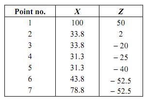
The precautions that need to be used in the use of these compensation codes are exactly same as those that need to be observed in machining centre programming. The coordinates of the contour are given in Table 3. The program segment for the same would be as follows:
Table 3
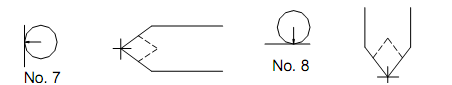
The tool-offset file was shown with a separate column for tool nose radius directions. When the tool nose radius compensation is to be specified, it is necessary to specify the correct directions. These specify the correct orientation of the tool with respect to the workpiece surface that is being generated. The meaning of the various codes is given in Figure 53.
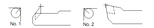
ID back boring and facing ID boring and facing
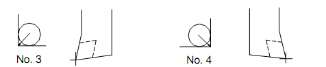
OD Turning and facing ID back turning and facing
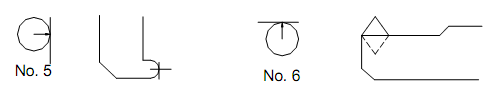
OD back face grooving ID profiling
Face profiling and grooving OD profiling
Figure 53: Tool Nose Radius Correction Directions and their Utilisation for Specific Machining Types