Programming Methods
The typical axis arrangement of a turning centre is shown in Figure 25. As explained earlier, the spindle axis is designated as Z while the radial axis perpendicular to the Z and away towards cutting tool is termed X-axis.
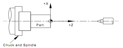
Figure 25: Axes System used for Turning Centres
The actual datum will need to be defined similar to the machining centre. The machine may have a fixed datum termed as home located generally at the intersection of the spindle axis and the clamping plane. However, a component datum is normally decided by the programmer based on the part geometry. The most general datum fixed is that shown in Figure 25.
Figure 26 shows the tool as seen in the tool post, which is generally an indexable arrangement with 8 to 12 tool positions. Some of the locations are designated for the external turning operations while some others will be designated for machining the internal profiles. For the machining of the component part, the tool tip will be moved past the workpiece. However, the machine uses the tool datum as shown in Figure 26, which means that the programmer will have to provide the necessary offsets of the tool from its datum position to the tool tip as tool offsets.
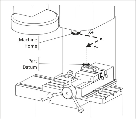
Figure 26 : The Tool Offsets that are Required for Each of the Tool Used