Field Layout and Installation
It is understood that the line (horizontal alignment) and grade layout of a sewer line as per design has to be carried out meticulously. The horizontal layout determines the location as well as direction of the sewer line, while slope (grade) of the line provides the necessary hydraulic carrying capacity of the sewerage system. The location of the trench is generally laid out first as an offset line running parallel to the proposed sewer centre line. This offset line is demarcated by wooden stakes driven into the ground surface at intervals of, say, 15 m. The offset line, as is clear, is quite away from the sewer centre line with a view not to allow it being disturbed during construction; however, it has to be proximate enough so that the transfer of measurements to the actual trench can readily be done. The wooden stakes are set with their tops at a specific height above the designed trench bottom (horizontal slope line) – thus, the checking of the trench depth during excavation, etc. can be done with ease.
Two procedures are available to lay pipe sections in the open trench, namely, by batter boards, and by laser beams. Better boards are placed across the trench at uniform intervals (Figure 17). The tops of these boards can be set at some even height above the designed sewer invert elevation. The centre line of the sewer is traced on the borads by extending a line of sight with a transit level or a theodolite and a string is stretched from board to board along this very line. Later on this line is transferred onto the trench bed by means of a plumb bob. Invert levels are lines that transferred onto the trench bed by means of a plumb bob. Invert levels are indicated by vertical rods marked off in even increments – the lower end of each rod is placed on the pipe invert, and the string over the batter boards helps to check if it matches with the proper elevation mark on the rod, by appropriate adjustment of the pipe placement.
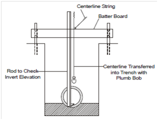
Figure 17: Laying of a Sewer Using Batter Boards
In the laser method, advantage is taken of an intense, narrow beam of light that is projected by the laser instrument, over a long distance. This beam is aligned through a sewer pipe to strike a target held at the other end of the pipe as shown in Figure 18. A transit that is placed above a manhole helps establish the alignment of the sewer with reference to field survey points, and transfer it down to the laser instrument that is mounted inside the manhole. Lasers can achieve an accuracy of 0.01 per cent over a distance of upto 300 m.
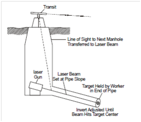
Figure 18: Laser Beam Used to Fix the Longitudinal Slope of a Sewer