MO diagrams
Diagram 2 depicts an MO diagram for H2. The AO energies of two isolated atoms are shown on the left- and right- hand sides and in the center are displayed the bonding and antibonding MOs resulting from their overlap. They are entitled as 1sσg and 1sσu, correspondingly, the σ title referring to their symmetric nature about the molecular axis and g and u (from the German gerade and ungerade, correspondingly) to their even or odd behavior under inversion via the center of symmetry of molecule (the mid-point of the bond, ).
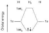
Fig. 2. MO diagram for H2 showing the bonding MO occupied by two electrons with paired spins.
Occupation of MOs is managed by the Pauli Exclusion Principle. In diagram. 2 two electrons are displayed with reverse spin (one upward and one downward pointing arrow) subsequent to the electron configuration (1sσg)2. While more than two electrons are exists some must take an orbital of higher energy. So He2 (four electrons) would have the electron configuration (1sσg)2(1sσu)2, which could be represented on a identical MO diagram. Calculations display that the increase of energy (relative to isolated AOs) in forming the antibonding MO more than compensates for the stabilization of the bonding MO. So, He2 is an unstable molecule with higher energy than two individual He atoms. In the MO theory 'repulsion' between closed shells (the He core in this example) is seen to be a consequence of the exclusion principle, that forces occupation of antibonding as well as bonding orbitals.
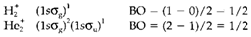
The definition of bond order (BO) in MO theory identifies that a 'normal' single bond is created by two electrons. We describe it as follows
BO=(1/2)[(number of electrons in the bonding MOs) -(number of the electrons in antibonding MOs)]
In the above instances, H2 and He2 have bond orders of one and zero, correspondingly. Fractional values are feasible, like in the molecular ions and which are both bonded but more weakly than H2, like indicated by the electron configurations and BO displayed below: