Brinell Hardness
This is a technique of indentation hardness which as its introduction in 1990 year via J. A. Brinell has been widely accepted for technological reasons. This method employs a steel ball of 10 millimeter diameter like indenter. The indenter is initially placed upon the surface that hardness is to be measured and after that a gradually raising load of 3000 kgf is applied upon the indenter. While the load is removed an indentation is left on the surface. For softer metals a lower 500 kgf load is applied to ignore extremely deep indentation and for Harder metals the steel ball is replaced via a tungsten carbide indenter hence indenter is not deformed. In each condition the load is applied for a standard time, commonly 30 sec. Following figure shows the indented and indenter plate
The indentation diameter is measured via a low power microscope. From the knowledge of the indentation diameter and spherical surface diameter of the indentation that will be equal to the diameter of the ball, the area of the spherical surface of the indentation could be computed. After that the ratio of the load which reasoned the indentation to the area of indented surface is explain as the Brinell hardness number or BHN.
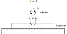
Figure: The test piece and Ball Indenter for Brinell hardness
Whether P = Applied load, kgf,
D = diameter of the ball, millimeter, and
d = diameter of the indentation, millimeter.
After that,
BHN = 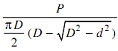 .....................Eq(3)
Though, from the definition and Eq. (3) it is understandable BHN has units of kgf/mm2, this does not express and physical meaning since the load P is not uniformly distributed above the indented surface.
The BHN value acquired for a material is fairly reproducible offered the load P and diameter D is similar for each test. To acquire the similar BHN at any other load the ratio d/D should be constant that requires that P/D must be constant. Hence for P = 3000 kgf, D = 10 millimeter, P/D = 30. Hence if a load of 2000 kgf is to be employed the ball diameter must be 8.15 millimeter, and for a 1 millimeter diameter indenter a load of 30 kgf must be employed.
The computed value of BHN might be slightly in error due to the assumption that the diameter of indented surface is similar as that of indenter that is not exactly true. After the removal of the load, several elastic recoveries take place whereby the final diameter of the surface becomes not same than ball diameter. Elastic recovery is greater than for softer materials for harder materials.
An anomaly may happen in measurement of indentation diameter of diameter, d, because of localized deformation of metal in the region of indentation. Following figure (a) shows the cross- section via indentation in a cold-worked metal. Since such a metal has little capacity to pile up to strain harden the metal has a tendency along the edge of impression.
This behaviour is called as "ridging" or "pilling up". Though the measured d is larger than real diameter of indentation, still the hardness is computed on the basis of measured d like shown in following figure (a) since the ridge also carries part of the load.
Following figure (b) shows the "sinking in" of an annealed metal. Around the edge of metal depression will apparently raise the diameter of the impression. To appear at the true value of d, the indenter is frequently coated via a dye before making the indentation. The diameter after that can be measured upon the coloured ring.
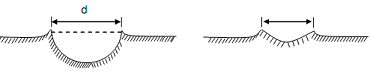
Figure: Cross-section through Brinell Indentation Showing on two dissimilar Materials:
(a) Ridging; and (b) Sinking In
Whilst making indentation on a plate specimen care should be exercised to ignore any interference among the edge of specimen and the indentation and the interference between two indentations. For this purpose it is advisable such the centre of the indentation should be at least 1.5 D absent from any edge. Similar distance should be maintained in between two neighboring indentations. Likewise the thickness of the plate should be at least equivalent to the diameter of indenter hence the plastically deformed zone underneath the indentation does not interfere along with the back surface.