Capacitive Reactance:
Capacitive reactance is the opposition though a capacitor or a capacitive circuit to the flow of current. The current flowing in a capacitive circuit is directly proportional to the capacitance and to the rate at which the applied voltage is changing. The rate at that the applied voltage is changing is determined through the frequency of the supply; thus, if the frequency of the capacitance of a provided circuit is increased, the current flow will increase. It could also be said in which if the frequency or capacitance is increased and the opposition to current flow decreases; thus, capacitive reactance that is the opposition to current flow that is inversely proportional to frequency and capacitance. A Capacitive reactance XC, is measured in ohms, as is inductive reactance. A mathematical representation In the Equation (8-3) for capacitive reactance
XC = 1/ 2ΠfC (8-3)
where
f = frequency (Hz)
Π = ~3.14
C = capacitance (farads)
The given Equation is the mathematical representation of capacitive reactance when capacitance is expressed in microfarads (µF).
XC = 1,000,000/2ΠfC (8-4)
Equation (8-5) is the mathematical representation for the current in which flows in a circuit along with only capacitive reactance.
I = E/XC (8-5)
where
I = effective current (A)
E = denotes for effective voltage across the capacitive reactance (V)
XC = capacitive reactance (?)
Example: A 10µF capacitor is connected to a 120V, 60Hz power source. Find out the capacitive reactance and the current flowing in the circuit and Draw the phasor diagram.
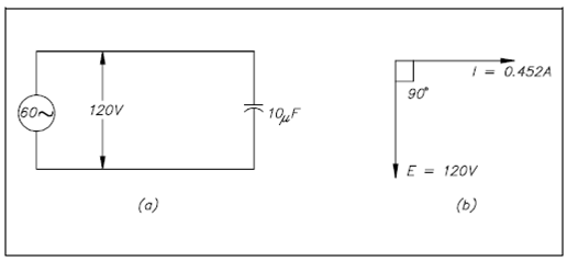
Figure: Circuit and Phasor Diagram
Solution:
1. Capacitive reactance
XC = 1,000,000/2Π fC
= 1,000,000/ (2)(3.14)(60)(10)
= 1,000,000 /3768
XC = 265.4?
2. Current flowing in the circuit
I = E/ XC
= 120/ 265.4
I = 0.452 amps
3. Phasor diagram displaying current leading voltage through 90° is drawn in Figure.