Turbo shaft engines :
Gas turbine engines that deliver power through a shaft to operate something other than a propeller are referred to as turboshaft engines. In most cases the output shaft (power takeoff), is driven by its own power turbine (free turbine), which extracts the majority of the total power output from the engines gas generator. Turboshaft engines with a reduction gear are used to power boats, ships, hovercraft, trains and cars. They are also used to pump natural gas across country and to drive various kinds of industrial equipment such as air compressors or large electric generators.
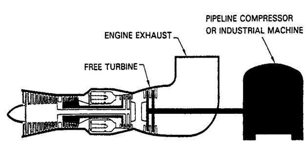
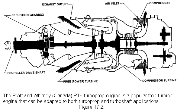
In aviation turboshaft engines are used to power many of the modern helicopters in service. They are similar in design to turboprop engines and in some instances will use the same gas generator section design. The turboshaft power takeoff may be coupled to, and driven directly by the turbine that drives the compressor, but is more likely to be driven by a turbine of its own. Engines using a separate turbine for power takeoff are called free power turbine engines, and it is this type of engine that is most commonly used in today's modern fixed wing and rotary wing aircraft. Atypical example of a turboprop/turboshaft engine is the Pratt and Whitney PT 6.
A free power turbine engine consists of two main units; the gas generator and the free power turbine. In the example shown in Figure. air enters the engine and is compressed, then heated in the combustion chamber . The resulting expansion forces the gas at high velocity through the gas generator turbine that drives the compressor. The remaining gas energy is then used to drive the power turbine, which in turn drives the power output shaft.
The free power turbine is mechanically independent of the of the gas generator and operates at virtually a constant speed. The power developed by the turbine is varied to meet changing loads imposed on the rotor system, by increasing or decreasing the fuel supplied to the gas generator, thus altering the gas generator speed and the supply of gas energy to the power turbine.
As mentioned previously, the turboshaft engine is used to power many of today's modern helicopters, and to this end we will concentrate on the application of the turboshaft engine in the field of aviation.
The turboshaft engine and the helicopter are ideal companions. The engine is required to respond to frequent and sudden changes in power demands to keep the helicopter rotor revolving at a virtually constant speed (250-300 RPM being typical). The power required to drive the rotor is determined by the pitch angle of the main rotor blades, this angle is being controlled by the pilot using the collective pitch lever. The pilot changes the flight path of the aircraft by using the cyclic pitch control lever, by tilting the rotor head. Control of the tail rotor to compensate for the torque produced by the main rotor is via foot pedals similar to rudder pedals. Whenever a control is activated, the resultant force is sensed by the rotor gearbox and in turn sensed by the power output shaft of the engine which means that the engine power must be adjusted to suit.
The power output of a free power turbine engine can be changed rapidly because its output speed is independent of the power produced, the latter being dependant on the gas generator speed. The low inertia of the gas generator rotor allows its speed to be changed very quickly, by adjusting the flow of fuel available for combustion. This is achieved in the fuel control system invariably by a computer (electronic or mechanical) controlling the throttling valve. The pilot selects the rotor speed and the fuel control system automatically maintains that speed, within the limits set by the governing characteristics of the system and the operating limitations of the engine. As the fuel control system is automatic, the pilot is relieved of the necessity to constantly manipulate the throttle control.