Thrust reversal - aircraft design, Other Engineering

Assignment Help:

Thrust reversal:

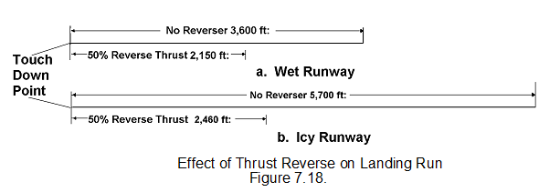
Thrust reversal is a means of reducing the landing run of an aircraft without excessive use of wheel brakes or the use of braking parachutes.  On a propeller driven aircraft (piston and turbo prop), reverse thrust can be obtained by reversing the pitch of the propellers.  On a pure turbo-jet this is not possible and the only simple and effective way of slowing the aircraft down quickly is to reverse the power as a deceleration force.  This method is much safer than wheel brakes when landing on ice or snow covered runways. 

It can on some aircraft also be used to reduce speed in flight thus allowing a rapid rate of descent without an air brake system.  The difference in landing distances between the same aircraft without reverse thrust and using reverse, is shown.

227_thrust reversal.png

To obtain reverse thrust, the jet efflux must be given a forward component of velocity.  The mechanism to achieve this should fulfil the following requirements:

a. A reasonable amount of thrust (50% of take-off thrust would be adequate) should be available in the reverse direction.

b. The reverser should not affect the normal working of the engine and there should be no appreciable loss of thrust or increase in specific fuel consumption (SFC).

c. When in use, the reverser should not cause debris or excessive amounts of hot air to enter the intake.

d. The discharged hot gases should not impinge on parts of the aircraft (eg. nacelles, tyres, landing flaps, cabin windows, etc.).  Impingement of the turbulent gas stream may cause damage by vibration as well as by heating. 

e. Fire hazards must be avoided.  Hydraulic and lubricating systems should not be fitted near the jet pipe.

f. Weight, complexity and cost must be kept to a minimum.

g. The reverser must not operate until required to do so.  It is necessary to ensure that:

1. Accidental selection of reverse thrust is impossible.

2. No single failure in the operating system selects reverse thrust.

3. The thrust changing elements are biased away from the reverse thrust position.


Related Discussions:- Thrust reversal - aircraft design

Diod, i donot under stand about diod and transistor

i donot under stand about diod and transistor

Electronics devices and circuits, With the help of circuit diagram and the ...

With the help of circuit diagram and the waveforms,explain the working of a negative clipper with positive biasing voltage.also explain the Same concept in series clipper circuit

Noise reduction in aircraft design, Noise reduction The problem of engi...

Noise reduction The problem of engine noise has always been associated with aircraft. Increases in engine power have given rise to increases in noise and the indications are t

Methods of forging, Q. Describe briefly the following methods of forging : ...

Q. Describe briefly the following methods of forging :        (i) Drop forging        (ii) press forging Ans.  (i) Drop Forging: It is also called die

Guides for the fire risk assessment, Guides for the fire risk assessment: ...

Guides for the fire risk assessment: In the UK, the Government produce guides for the FRA process that are free to download.   There are a range of guides covering  the ran

Aerodynamics-supercritical aerofoils, Design Features of Supercritical Aero...

Design Features of Supercritical Aerofoil • Blunt nose- rapid p pressure reduction around leading edge • Flat top- Reduce the flow acceleration on upper surface toreduc

Diffuser action-aircraft maintance, Diffuser action: The flare, which i...

Diffuser action: The flare, which increases the area of the duct, is known as a diffuser and its shape determines the rate of compression and the amount by which the air is com

Need answers in an excel spreadsheet, 1 Scott Investors, Inc., is consideri...

1 Scott Investors, Inc., is considering the purchase of a $447,000 computer with an economic life of five years. The computer will be fully depreciated over five years using the st

Avionic systems design- primed stability derivatives, Primed stability der...

Primed stability derivatives The rolling and yawing motions are coupled through the cross inertia I XZ due to rotation not being about the principal axes. Since in general air

Write Your Message!

Captcha
Free Assignment Quote

Assured A++ Grade

Get guaranteed satisfaction & time on delivery in every assignment order you paid with us! We ensure premium quality solution document along with free turntin report!

All rights reserved! Copyrights ©2019-2020 ExpertsMind IT Educational Pvt Ltd