Stress-strain carves for ductile materials, Mechanical Engineering

Assignment Help:

Stress-strain carves for ductile materials:

A material is said to be ductile in nature, if it elongates before fracture. One this type of material is mild steel. Shape of stress strain diagram for mild steel is shown in the figure given below.

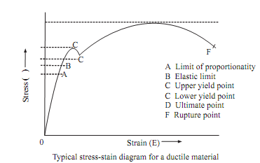
A mild steel specimen of circular cross section or rectangular section is pulled until it breaks. The extensions of bar can be measured at every load increments. The stresses can be calculated based on the original cross sectional area and strains by dividing extensions by gauge length. When specimen of a mild steel is loaded in tension gradually, increasing tensile load, in the tension testing machine. The initial portion from O to A is linear where the strain linearly varies with stress. The line is called as line of proportionality and is known as proportionality limit. The stress corresponding to point is known as Limit of Proportionality. Hook's law obeys in this, slope of line gives, modulus of elasticity.

Further any increase in load increases extension rapidly and the stress strain diagram becomes curved. At the point B, material reaches elastic limit of it indicating end of elastic zone and entry into plastic zone. In most cases A and B coincide. If load is removed material returns to original dimensions of it.

Beyond elastic limit, the material enters into plastic zone and removal of load does not return specimen to its original dimensions, therefore subjecting the specimen to permanent deformation. On loading further the curve reaches the point 'C' called as upper yield point at which sudden extension occurs which is called as ductile extension where strain increases at constant stress. This can be identified by horizontal portion of the diagram. Point C gives yield stress beyond which load decreases with increase in strain up to C called as lower yield point.

After lower yield point has been crossed, stress again begins increasing, till stress reaches the maximum value at the point 'D'. The increase in load causes non linear extension up to point D. The point D called as ultimate point or maximum point. This point gives ultimate strength or maximum load of bar. The stress corresponding to highest point 'D' of stress strain diagram is called as ultimate stress.


2365_Stress-strain carves for ductile materials.png


Related Discussions:- Stress-strain carves for ductile materials

Determine strap beam with suitable demonstration, Determine strap beam with...

Determine strap beam with suitable demonstration. Here observe that R e becomes greater than P e by a magnitude of V while R i becomes less than P i by a magnitude equal to

Steam , how to calculate the volume of HFO burn to produice steam?

how to calculate the volume of HFO burn to produice steam?

Calculate the minimum thickness, A circular thin steel diaphragm having an ...

A circular thin steel diaphragm having an effective diameter of 20mm is clamped around its periphery and is subjected to a uniform gas pressure of 180kN/m^2. Calculate the minim

Tank drainage-apparent viscosity-laminar flow, Tank Drainage A large op...

Tank Drainage A large open vertical tank has three small, smooth, well-rounded orifices spaced equidistantly at ¼ h , ½ h , ¾ h up from the bottom of the tank (Fig. Q1). Water

Stroke -engine terminology , Stroke: The nominal distance through which a...

Stroke: The nominal distance through which a working piston moves between two successive reversals of its direction of motion is called the stroke and is designated by the letter

Determine the percentage savings in the material, Determine the percentage ...

Determine the percentage savings in the material: A hollow shaft containing an inside diameter 0.5 times the outer diameter is to replace the solid shaft of the similar materi

How is rending stress designed in plain concrete footing, How is rending st...

How is rending stress designed in plain concrete footing? Rending Stresses Also design the plain concrete footing based on bending moment and shear considerations. In wall f

What are the several factors affecting tool life, (a) Draw a single point c...

(a) Draw a single point cutting tool and label clearly the several parts of it. Illustrate them in brief. (b) What are the several factors affecting tool life ? (c) List char

Explain the primitive instancing, Primitive Instancing In primitive ins...

Primitive Instancing In primitive instancing, the modeling system defines a set of primitive 3D solid shapes that are relevant to the application area. Primitive instances are

Explain the intensive properties of a system, Explain the Intensive Propert...

Explain the Intensive Properties of a System Intensive properties are those, which have similar value for any part of the system or the properties which are independent of the

Write Your Message!

Captcha
Free Assignment Quote

Assured A++ Grade

Get guaranteed satisfaction & time on delivery in every assignment order you paid with us! We ensure premium quality solution document along with free turntin report!

All rights reserved! Copyrights ©2019-2020 ExpertsMind IT Educational Pvt Ltd