As an instance of the normal priority mode, imagine that initially AEOI is equal to 0 and all the ISR and IMR bits are clear. Also consider that, as shown in given figure, requests occur concurrently on IR2 and IR4, then a request arrives at IRI, and finally a request arrives at IR3 and that these are the only requests. First of all, ISR2 will be set and the interrupt routine link with IR2 will begin executing. After this routine resets the IF flag to value 1 and when the IRI request, ISRI will be set and the IRI routine will be executed entirety. Whenever it is executing it should reset the IF bit to value 1 and send the essential command to clear ISRI. Upon the return to the IR2 routine, ISR2 is cleared and then ISR4 is set and its routine is started. While this routine is executing IR3is made. It is acknowledged immediately when the IF is reset to value 1, and ISR3 is set. Then the IR3 routine is started. Before the IR3 routine is ended it should clear ISR3 and set IF. The return is made to the IR4 routine, which should be clear ISR4 before the returning to the IR2 routine. The IR2 routine, that already has cleared the ISR2 bit, would easily return to the interrupted program. (Note that if IF is not reset to the value 1 within the interrupt routine, further then interrupts will not be processed till the routine is completed, for instance, the IRET instruction is encountered.)
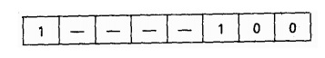
Although a 1 s is sent to bit 5 of OCW2 usually causes the highest-priority ISR bit (for instance, the last ISR bit to be set) to be cleared, any ISR bit may be explicitly cleared by sending an the OCW2 with the SL, R and EOI bits set to Oil and putting the number of the bit to be cleared in L2-L0. If is sent to the OCW2, then ISR3 will be cleared.

Additionally to the normal priority mode discussed above, OCW2 may rotate the priority by assigning bottom priority to any one of the IR levels. In this kind of case the other priorities will follow as if the normal ordering had been rotated. i.e. If the lowest priority is given to IR4, then the order of priorities will be as following:
IR5, IR6, IR7, IR0, IR1, IR2, IR3, IR4
(For instance IR5 is rotated into the top-priority position). A rotation by one may be obtained by allowing the combination for the R and SL bits be value 10. If the R and SL bit combination is II, then the IR level with the lowest priority is the one indicated by L2-LO. If IR5 currently has top priority and

It is sent to the OCW2, then the new priority ordering would be
IR6, IR7, IR0, IR1, IR2, IR3, IR4, IR5
It is sent, the new ordering would be
IR3, IR4, IR5, IR6, IR7, IR0, IR1, IR2
The R and SL bits can also have importance when EOI is equal to 0. In this case R is set 1 and SL is set to value 0 cause automatic rotations when AEOI is equal to 1, and R = SL = 0 turns off this action so that automatic rotations do not take place. R = SL = 1 and EOI is equal to 0 result in the lowest priority being designated by L2-LO without an EOI command being sent. The remaining combination, R = 0 and SL = 1, which causes no action.
In OCW3, SMM (special mask mode) bits and the ESMM (enable special mask mode) can be utilized to negate the priority modes describe above. If a byte is sent to the OCW3 in which both the ESMM and the SMM are set to value 1, then unmasked interrupt requests are processed as they arrive (provided that the processor's IF bit is value1) and the priority order is avoided. By sending subsequently a byte to the OCW3 in which ESMM is equal to value 1 and SMM is equal to value 0, a switch back to the priority ordering of interrupts might be made. If a byte with the ESMM bit equal to value 0 is sent to the OCW3, then the SMM bit will have no effect and the special mask mode will not be change.
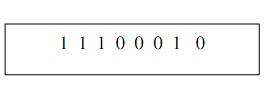
The P (polling) bit is used to place the 8259A in polling mode. This mode assume that the CPU is not accepting interrupts (IF = 0) and it is compulsory for the interrupt requests in the IRR to be polled. When the P bit is value 1 the next RD signal would cause" the suitable bit in the ISR to be set just as if INTA signal had been received, and it would return to the AL register in the CPU a byte of the form
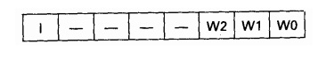
Where I = 1 show that an interrupt is present and W2, W0, and W1 give the IR level of the highest- priority interrupt. For instance, if P = 1, the priority or daring is
IR3, IR4, IR5, IR6, IR7, IR0, IR1, IR2 there are unmasked interrupts on IRI and IR4, and the instruction
IN AL, 80H
(Where 0080 is the even address of the 8259A) is executed, then
It is input to the AL register.
When P = 0, the contents of IRR or ISR might be read into the AL by setting RR = 1 and executing the instruction
IN AL, 80H
If at the same time the IN instruction is executed RIS is equal to 0, then IRR is input; or else, ISR is read. The contents of IMR might always be read, using the of 8259A, for example:- for the address assignment denoted above,
IN AL, 81H
It would input the contents of IMR to AL.
Because OCW3 bits (except for ESMM) are utilized to indicate whether or not the 8259A is in special mask mode and which information is to be put on the data bus during a read instruction, these bits are retained till they are reset by the next output to OCW3. For example, if P = 0= RIS and RR = 1 any read from the even address of the 8259A before a new byte is sent to OCW3 will cause IRR to be read.