Resultant air-gap flux of induction machine, Electrical Engineering

Assignment Help:

Q. Resultant air-gap flux of induction machine?

The resultant air-gap flux is produced by the combined mmfs of the stator and rotor currents. For the sake of conceptual and analytical convenience, the total flux is divided into a mutual flux (linking both the stator and the rotor) and leakage fluxes, represented by appropriate reactances.

Considering the conditions in the stator, the synchronously rotating air-gap wave generates balanced polyphase counter emfs in the phases of the stator. The volt-ampere equation for the phase under consideration in phasor notation is given by

83_Resultant air-gap flux.png

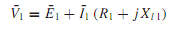
where ¯ V1 is the stator terminal voltage, ¯ E1 is the counter emf generated by the resultant air-gap flux, ¯I1 is the stator current, R1 is the stator effective resistance, and Xl1 is the stator-leakage reactance.

1835_Resultant air-gap flux1.png

As in a transformer, the stator (primary) current can be resolved into two components: a load component ¯I2 (which produces an mmf that exactly counteracts the mmf of the rotor current) and an excitation component ¯I0 (required to create the resultant air-gap flux). This excitation component itself can be resolved into a core-loss component ¯ Ic in phase with ¯E1

and a magnetizing component ¯Im lagging ¯E1 by 90°. A shunt branch formed by the core-loss conductance gc and magnetizing susceptance bm in parallel, connected across ¯E1, will account for the exciting current in the equivalent circuit, as shown in Figure, along with the positive directions in a motor.


Related Discussions:- Resultant air-gap flux of induction machine

Total debt to total assets ratio, Total Debt to Total Assets ratio A m...

Total Debt to Total Assets ratio A metric used to measure a company's financial risk by determining how much of the company's assets have been financed by debt. It is calculat

Give illustration of and and or gate - microprocessor, Give Illustration of...

Give Illustration of AND and OR Gate - Microprocessor? Illustration: The image below demonstrate the 4 possible inputs into a 2-input AND gate and all the corresponding outputs

Diode, positive diode and negtive diode cliping

positive diode and negtive diode cliping

Semiconductors, Why do potential barriers breaks when a breakdown voltage i...

Why do potential barriers breaks when a breakdown voltage is application to semiconductor

Structure and use of pnp transistor, Structure and use of PNP transistor: ...

Structure and use of PNP transistor: The figure opposite is a schematic presentation of a PNP transistor related to two voltage sources. To construct the transistor conduct ap

Explain about register marker, Q. Explain about Register marker? Regist...

Q. Explain about Register marker? Register marker: Stronger selectors perform searching and counting . Though, the crossbar switch has no ‘intelligence'. Something external to

Determine rc in given figure, Q. Afixed-biasmethod is illustrated in Figure...

Q. Afixed-biasmethod is illustrated in Figure. Assuming ICBO to be small compared to I BQ and I CQ , find RB such that the operating point corresponds to I CQ = 14 mA, V CEQ = 7

Difference between div and idiv instructions, Mention how do the DIV & I...

Mention how do the DIV & IDIV instructions differ in their functionality DIV: Unsigned numbers division and IDIV: Signed number division.

Write Your Message!

Captcha
Free Assignment Quote

Assured A++ Grade

Get guaranteed satisfaction & time on delivery in every assignment order you paid with us! We ensure premium quality solution document along with free turntin report!

All rights reserved! Copyrights ©2019-2020 ExpertsMind IT Educational Pvt Ltd