Reduction Gearing :
Compound epicyclic reduction gears enable a greater reduction in speed to be obtained without resorting to larger components. They may be of either the fixed or free annulus type.
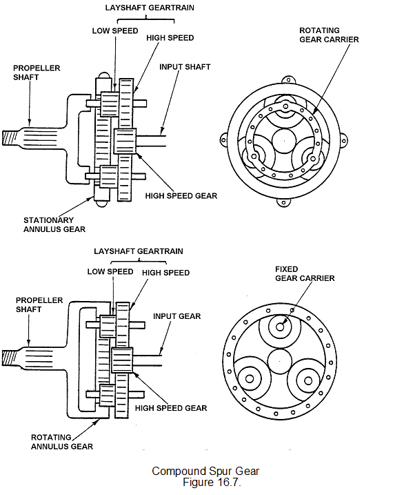
GEAR TRAIN/EPICYCLIC
Some turbo-props will use a gear train or a combination of gear train and epicyclic.
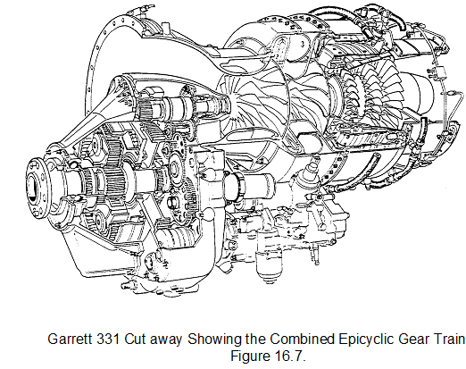
TURBO-PROP PERFORMANCE
The turbo-prop has a higher propulsive efficiency than the turbo-jet up to speeds of approximately 575 mph and higher than a turbo-fan engine up to approximately 450 mph. Compared with a piston engine of equivalent power, the turbo-prop has a higher power/weight ratio and a greater fatigue life because of the reduced vibration level from the gas turbine rotating assemblies.
TURBO-PROP ENGINE CONTROL
The gas generator element of the turbo-prop engine operates at high rpm for maximum efficiency; any reduction in rpm reduces the pressure ratio across the compressor and therefore adversely affects the sfc. In practice, most turbo-prop engines have gas generators which run at or near 100% rpm and three main methods are used to control the rpm and power absorption of the propeller throughout the normal flight ranges. These are:
• Integrated control of both rpm and fuel flow.
• Direct control of gas generator fuel flow.
• Direct control of propeller blade angle.
INTEGRATED CONTROL OF RPM AND FUEL FLOW
The integrated control system is suitable for coupled power turbine and compounded turbo-prop engines. In this system the propeller rpm is selected by a power lever that simultaneously adjusts the fuel flow to ensure that the correct flow is maintained for any selected rpm. Up to maximum rpm, the turbo-prop runs at the selected rpm, increases in rpm demanded by the power lever being automatically accompanied by corresponding increases in fuel flow, blade angle and hence power. At maximum rpm, further increases in power are achieved by increasing the fuel flow; the propeller constant speed unit (CSU) automatically increases the blade angle to absorb the extra power and thus maintain constant speed.
DIRECT CONTROL OF FUEL FLOW
The direct control of fuel flow is suitable for use in a free power turbine engine. In this system, the gas generator is controlled in the same manner as a turbo-jet and the power available to the free turbine assembly is governed by the fuel flow. Through reduction gearing, the free turbine turns the propeller that is maintained at constant rpm by the CSU.
DIRECT CONTROL OF BLADE ANGLE (BETA CONTROL)
This control system can be used for any turbo-prop engine. In this system, the cockpit power lever simply selects a blade angle (B) and various automatic systems are used to maintain the propeller rpm by adjusting the fuel flow (e.g. by a governor in the fuel control system). The Astazou engine in the Jetstream is typical of the direct-coupled engine in which this control system is used. As the propeller blade angle is changed, the propeller speed governor adjusts the fuel flow to maintain constant propeller rpm (and thus constant engine rpm). The direct control of blade angle in a free turbine system is found most commonly in helicopter turbo-shaft engines. Here, the blade angle is selected by the collective lever and the output of the gas generator is automatically adjusted to maintain the rotor rpm within fine limits.