Propeller shafts, Other Engineering

Assignment Help:

PROPELLER SHAFTS

Most modern engines, both reciprocating and turbine, have flanged propeller shafts. Some of these flanges have integral internally threaded bushings that fit into counterbores in the rear of the propeller hub around each bolt hole. Propellers with these bushings are attached to the shaft with long bolts that pass through the propeller. On others the flange has a ring of holes and bolts pass from the engine side into threads in the propeller.

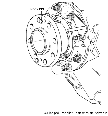
Some flanges have index pins in the propeller flange so the propeller can be installed in only one position relative to the shaft this done for synchronising and/or synchrophasing.

2130_propller shaft.png

The most popular type of propeller shaft on reciprocating engines built through World War II and on the larger turboprop engines is the splined shaft. The sizes of splined shafts are identified by an SAE (Society of Automotive Engineers) number, SAE 20 splines are used on engines in the 200-horsepowered range; SAE 30 splines are used in the 300- and 400-horsepowered range, and SAE 40 in the 500- and 600-horsepowered range. SAE 50 in the 1,000-horsepowered range and SAE 60 and 70 are used for larger engines.
864_propller shaft1.png

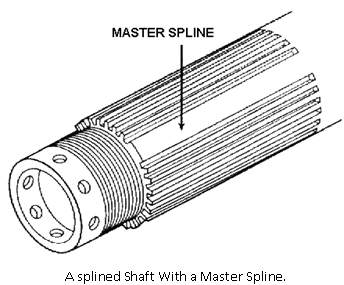
Splines are longitudinal grooves cut in the periphery of the shaft. The grooves and lands (the space between the grooves, are the same size, and one groove is either missing or has a screw in it to form a master spine. The purpose of the master spline is the same as the index pin.

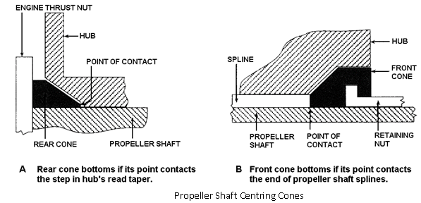
The inside of the propeller hub is splined to match the shaft and the hub is centred on the shaft with two cones. The rear cone is a single-piece split bronze cone, and is considered to be part of the engine. The front is a two piece hardened steel cone and is considered to be part of the propeller. The two halves are marked with the same serial number to ensure that only a match set is used. Prior to attaching a this type of propeller, a check is carried out to ensure correct contact of the cones. Engineers blue is applied to the cones and the propeller is fitted and torqued up, the propeller is then removed and there should be an even 80% contact around the cone on the propeller as seen by the blue, if there is not the cone can be stoned to fit, or replaced.

1955_propller shaft2.png


Related Discussions:- Propeller shafts

Clipper and clamper, i want 5 question for clipper and clamper along with t...

i want 5 question for clipper and clamper along with their solution

Finance Project, You are interested in proposing a new venture to the manag...

You are interested in proposing a new venture to the management of your company. Pertinent financial information is given below. BALANCE SHEET Cash 2,000,000 Accounts Payable and

Composite materials - notation of axes, Notation for Body Axes The stan...

Notation for Body Axes The standard notation for the body axis sytem for aircraft dynamics. This sectionexplains the significance of the term body axis and develops the non-lin

Limited travel distances - means of escape, Limited travel distances - mean...

Limited travel distances - means of escape: Are travel distances within the maximum allowable distances published in the guidance? Is there good visibility in the

Duct with flow control-aircraft maintenance, Duct With Flow Control-Aircraf...

Duct With Flow Control-Aircraft maintenance: BERNOULLI'S THEOREM This theorem can be related to the relationship between pressure and velocity existing in the air flowing

Signal and system, if the response of a signal is h(t) then the cascading o...

if the response of a signal is h(t) then the cascading of two responses h1(t) and h2(t) is given by

Process of fire risk assessment in uk, Process of fire risk assessment: ...

Process of fire risk assessment: In the UK, the process for  the FRA came out of the process for a general risk assessment. In a general risk assessment hazards are identif

Controller requirements, Controller Requirements  The requirements for ...

Controller Requirements  The requirements for the stability and performance of fight control systems are specified in the certi-fication requirements for U.S. civilian aircraft

Blow hole and pin hole porosity, Blow Holes                    (i) Exc...

Blow Holes                    (i) Excessive moisture in the moulding sand.                   (ii) Low permeability and excessive fine grain sands.                   (iii

Write Your Message!

Captcha
Free Assignment Quote

Assured A++ Grade

Get guaranteed satisfaction & time on delivery in every assignment order you paid with us! We ensure premium quality solution document along with free turntin report!

All rights reserved! Copyrights ©2019-2020 ExpertsMind IT Educational Pvt Ltd