PITCH LOCK MECHANISM
The pitch lock mechanism is necessary to cater for the two fine pitch position of 'flight fine pitch' and 'ground fine pitch'. It acts as a safety device designed to prevent the propeller from inadvertently over-running the flight fine pitch position to the detriment of flight safety.
PRINCIPLE OF OPERATION
The pitch change piston is fitted with two pitch stops - the flight fine pitch stop and the ground fine pitch stop. The flight fine pitch stop provides a normal fine pitch angle, whereas the ground fine pitch stop does not arrest the piston movement until the propeller blades turn into the plane of rotation to attain zero pitch angle. To obtain a zero blade angle it follows that the pitch change piston must move beyond the flight fine pitch position and, to achieve this, the flight fine pitch stop must be withdrawn or rendered ineffective whenever ground fine pitch is required. Therefore, the flight fine pitch stop is a flexible arrangement which requires a support to maintain it in the flight fine pitch stop position. When the support shown is withdrawn, the flight fine pitch stop can move down flush with the level of the pitch lock cylinder and the oil pressure acting upon the pitch change piston can now move it forward into the ground fine position. The pitch lock assembly fits inside the pitch change cylinder and the transfer sleeve housing where it connects with the oil tubes to complete the oilways to the PCM.
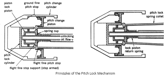
PITCH LOCK MECHANISM:
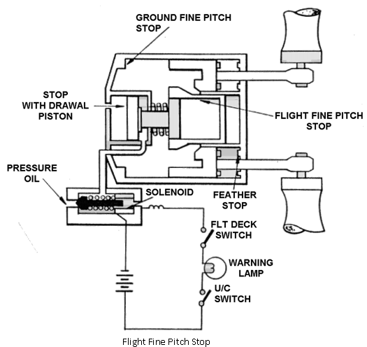
When the aircraft is on the ground the undercarriage switch is closed, the flight deck switch completes the circuit to energise the solenoid valve.
The open solenoid valve directs oil pressure to the stop withdrawal piston allowing the spring collect to spring inwards to remove the Flight Fine Pitch Stop.
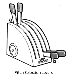
To enable either flight fine pitch or ground fine pitch to be selected, pitch selection levers are provides. These levers (one for each propeller) are fitted to the main control pedestal in the aircraft cockpit. They are called 'fine pitch stop levers' and they provide the two stop positions required for flight fine or ground fine. The lever position are:
• Stop armed - This is the flight fine position and the stop lever is at the front of the quadrant.
• Stop removed - This is the ground fine position and the stop lever is at the rear of the quadrant.
To prevent inadvertent loss of propulsive thrust, the pitch stop levers are mechanically inter-connected with the throttle lever so that when all throttle levers are advanced towards open (for max or cruise power) the pitch stop levers must move into the stop armed position. Thus always when the aircraft is flying the flight fine pitch stop is armed.