Partial derivatives - transistor hybrid model, Electrical Engineering

Assignment Help:

Partial derivatives - Transistor hybrid model:

The partial derivatives are taken by keeping the collector voltage or base current constant as pointed out by the subscript attached to the derivative.

ΔvB , ΔvC ,  Δ iC , Δ iB present the small signal(increment) base and collector voltages and currents, they are presented by symbols   vb , vc , ib and  ic correspondingly. 

 Eqs (3) and (4) may be written like as follow:

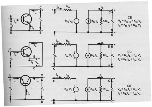
             Vb = hie ib + hre Vc                                                                 

              ic = hfe ib + hoe Vc

in which   hie =(∂f1/∂iB)Vc =  (∂vB/∂iB)Vc = (ΔvB /ΔiB)Vc = (vb / ib)Vc         

                  hre =(∂f1/∂vc)IB   =  (∂vB/∂vc) IB = (ΔvB /Δvc) IB = (vb /vc) IB


                hfe  =(∂f2/∂iB)Vc =  (∂ic /∂iB)Vc = (Δ ic /ΔiB)Vc = (ic / ib)Vc

                hoe= (∂f2/∂vc)IB   =  (∂ic /∂vc) IB = (Δ ic /Δvc) IB = (ic /vc) IB

The above equations described the h-parameters of the transistor in CE configuration. Similar theory can be extended to transistors in additional configurations.

Hybrid Model and Equations for the transistor in three dissimilar configurations are displayed below.

662_Partial derivatives - Transistor hybrid model.png


Related Discussions:- Partial derivatives - transistor hybrid model

What is the impulse response of this filter, Consider the filter h[n,m] des...

Consider the filter h[n,m] describing the input-output relationship below: g[n,m]=f[n-1,m]+ f[n,m-1]+ f[n+1,m]+ f[n,m+1] a)  What is the impulse response of this filter? b

#title. electronic project for invention, I need assistance in building a c...

I need assistance in building a circuit for my invention ,I am a electronic tech with limited knowledge but designing and building a proto model is a little out of my expertise ce

Compare dispersion effects single mode and multimode fibre, Compare dispers...

Compare dispersion effects in single mode and multimode fibres? The optical fibres were categorized within two according to the number of modes it passes as: • Single mode fibre

Find the frequency of oscillation - amplifier gain, Q. Find the frequency o...

Q. Find the frequency of oscillation, amplifier gain ? The transfer function is found to be where the equation is written as a Laplace transform (s=jw). Analysis of thi

Domestic financial system, Q. "Developing countries could delay opening the...

Q. "Developing countries could delay opening the capital account until the domestic financial system is strong enough to withstand the sometimes flow of world capital and violen

Frequency modulation, 1. Frequency Modulation theory and its explanation ...

1. Frequency Modulation theory and its explanation 2. FM transmitter schematic, tests results and measurements 3. Amplifier and Oscillator circuit explanation and calculation

Circuit theory, i want circuit theory relavant assingment sir please immed...

i want circuit theory relavant assingment sir please immediately

On line ups systems - power supplies , On line UPS Systems In this Ups ...

On line UPS Systems In this Ups  there are two  switches  one is  main static switch  and another  is Ups  static  switch . in normal  operation the Ups  static switch  remains

Write Your Message!

Captcha
Free Assignment Quote

Assured A++ Grade

Get guaranteed satisfaction & time on delivery in every assignment order you paid with us! We ensure premium quality solution document along with free turntin report!

All rights reserved! Copyrights ©2019-2020 ExpertsMind IT Educational Pvt Ltd