Generation of steam at constant pressure - thermodynamics, Mechanical Engineering

Assignment Help:

Generation of steam at constant pressure:

Steam is pure substance. Like any other pure substance it can also be converted into any of the three states, that is, solid, liquid and gas. A system which comprises of liquid and vapour phases of water is a pure substance. Even if some of the liquid is vaporised or some vapour get condensed during this process, the system will be homogeneous chemically and unchanged in chemical composition.

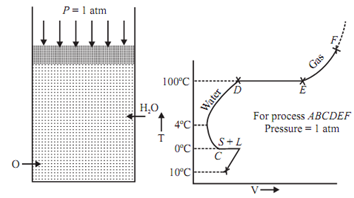
Assume that unit mass of steam is generated beginning from solid ice at -10°C and 1atm pressure in cylinder and piston machine. The distinct regimes of heating are as given below:

Regime (A-B) : The heat given to ice increases its temperature from -10°C to 0°C. The volume of ice increases with the increase in temperature. Point B explains saturated solid condition. At point B the ice starts melting.

Regime (B-C): The ice melts into water at constant temperature and pressure. At point C the melting - process ends. There is sudden decrease in volume at temperature 0°C as the ice starts melting. It is a peculiar property of water because of hydrogen bonding.

Regime (C-D): The temperature of water increases heating from temperature 0°C to 100°C. The volume of water 1st decreases with an increase in temperature, reaches to its minimum at 4°C

1878_Generation of steam at constant pressure.png

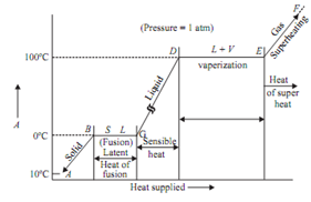
Point D shows saturated liquid condition.

Regime (D-E): The water starts boiling at D. The liquid starts getting into converted into vapour. The boiling stops at point E. Point E shows the saturated vapour condition at 100°C and 1 bar.

Regime (E-F): It shows the superheating of steam above saturated steam point. The volume of vapour increases quickly and it behaves as perfect gas. The difference between superheated temperature and the saturation temperature at a given pressure is called degree of superheat.

1785_Generation of steam at constant pressure1.png

Point B, C, D, E are known as saturation states.
State B: Saturated solid state. State C and D: Both saturated liquid states.

State C is for hoar frost and state D is for vaporization.
State E: Saturated vapour state.
At the saturated state phase can get changed without any change in pressure or temperature.


Related Discussions:- Generation of steam at constant pressure - thermodynamics

Determine the shear force and bending moment equation, Determine the Shear ...

Determine the Shear Force and Bending Moment Equation The 13-ft long beam ABCDE is simply supported with concentrated loads of 2000 lb at points A and D and a distributed

Age-hardening of aluminium alloys, Age-hardening of Aluminium Alloys I...

Age-hardening of Aluminium Alloys In specific alloys precipitation from a single phase may arise. The precipitate phase might be in form of determine sub-microscopic particles

Determine the brake mean effective pressure, A 4 cylinder petrol engine ope...

A 4 cylinder petrol engine operates on the 4-stroke cycle. The bore of each cylinder is 70mm and stroke 100mm. The clearance volume per cylinder is 60cm3. At a speed of 4000rpm, th

Spring, strain energy = m2l/2Ei

strain energy = m2l/2Ei

Can you explain corners and fillets, Q. Can you explain Corners and fillets...

Q. Can you explain Corners and fillets ? Corners and fillets The intersection of the surfaces in casting must be smooth and forms no sharp angles. For this, the external a

Indicator diagram and indicated power - thermodynamics, Indicator diagram a...

Indicator diagram and indicated power: An indicated diagram is graph between pressure and volume. The former being taken on the vertical axis and latter on the horizontal axis

Lubricating system, what are the functions of a lubricating system

what are the functions of a lubricating system

Material and tribology, The Cu-Sb system contains 2 eutectics, 1 eutectoid,...

The Cu-Sb system contains 2 eutectics, 1 eutectoid, 1 peritectic and 1 peritectoid. Mark them all on the figure, write down the temperature and composition of each point, and ident

Jib crane mechanism, Jib crane Mechanism: Sol.: Jib crane is taken i...

Jib crane Mechanism: Sol.: Jib crane is taken in use to raise heavy loads. A load W is lifted up by pulling the chain through pulley D as shown in the adjacent figure.

Write Your Message!

Captcha
Free Assignment Quote

Assured A++ Grade

Get guaranteed satisfaction & time on delivery in every assignment order you paid with us! We ensure premium quality solution document along with free turntin report!

All rights reserved! Copyrights ©2019-2020 ExpertsMind IT Educational Pvt Ltd