Fuel Distribution
During operation, fuel flows from the aircraft fuel tank to the fuel-pump boost-stage inlet. The pressurised fuel from the boost stage of the engine-driven fuel pump then leaves the pump and is delivered to the fuel/oil cooler, whose pur¬pose is to keep the fuel sufficiently warm to prevent ice from forming in the fuel, and at the same time, keep the maximum temperature of the oil within the correct limits. This engine is also equipped with an air/oil heat exchanger, which uses fan air and 2.5 bleed air to prevent the fuel from getting too hot.
From the fuel/oil cooler, the fuel is returned to the fuel pump, where it is filtered and sent to the main pump stage to be further pressurised before it is sent to the fuel-metering unit, which actually does the metering on the basis of infor¬mation it receives from the FADEC. The fuel-metering unit sends fuel to the fuel-flow transmitter, and then to the fuel distribution valve. (Servo fuel, used as an actuation pressure to some interface components, also comes from the fuel--metering unit.) Bypass fuel not sent to the fuel distribution valve or servo supply is returned to pump interstage flow. From the fuel distribution valve, the metered fuel flows through the fuel manifolds to the fuel injectors.
The FADEC is the primary interface between the engine and the aircraft. The FADEC contains two channels that are called "A" channel and "B" channel. Each time the engine starts, alternate channels will automatically be selected. The channels are linked together by an internal mating connector for crosstalk data transmission. Much more is accomplished by this control than simply sending a signal to the fuel-¬metering unit to establish a fuel flow to the nozzles.
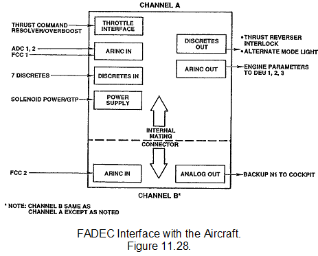
Interface with Aircraft
The FADEC receives several refereed (a validated refer¬ence used to confirm correct input) inputs and delivers sev¬eral outputs. Inputs to the FADEC come from the following:
1. The power levers. Two analogue signals come from each power-lever resolver. (The resolver is an electrome¬chanical device to measure angular movement.)
2. The air-data computers (ADC) in the form of
a. Total pressure
b. Pressure altitude
c. Total air temperature
3. The flight-control computer (FCC) for adjusting the engine pres¬sure ratio (EPR) for all engines as a part of the engine thrust trim system (ETTS). The ETTS logic starts when the engine pressure ratio (EPR) on any two engines is above 1.2.
4. Seven discrete (electrical signals) inputs:
- Pt2/Tt2 probe heat
- Fire
- Alternate mode select
- External reset (fuel-control switch)
- Bump rate selector
- Maintenance (data retrieval)
- Engine location identification
5. Two sources of 28 VDC power (DC bus and ground test power)
Out puts from the FADEC are as follows:
• Engine pressure ratio (EPR)
• Low-speed spool (NI). There is a backup N1 speed out¬put from channel "B."
• Exhaust gas temperature (EGT)
• High-speed spool (N2)
Flap/slat position and weight-on-wheels status is also sent to the FADEC. The flight-control computer (FCC) acts as a backup for the air-data computer (ADC).