Explain working of three-phase transformers, Electrical Engineering

Assignment Help:

Q. Explain working of three-phase transformers?

Transformation in three-phase systems can be accomplished in either of two ways: (1) connecting three identical single-phase transformers to form a three-phase bank (each one will carry one-third of the total three-phase load under balanced conditions); or (2) a three-phase transformer manufactured for a given rating. A three-phase transformer, compared to a bank of three single-phase transformers, for a given rating will weigh less, cost less, require less floor space, and have somewhat higher efficiency.

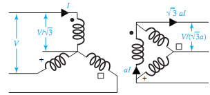
The windings of either core-type or shell-type three-phase transformers may be connected in either wye or delta. Four possible combinations of connections for the three-phase, two- winding transformers are Y- Δ, Δ -Y, Δ -Δ , and Y-Y. These are shown in Figure with the transformers assumed to be ideal. The windings on the left are the primaries, those on the right are the secondaries, and a primary winding of the transformer is linked magnetically with the secondary winding drawn parallel to it. With the per-phase primary-to-secondary turns ratio (N1/N2 = a), the resultant voltages and currents for balanced applied line-to-line voltages V and line currents I are marked in the figure.

2459_Explain working of three-phase transformers.png

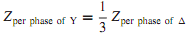
As in the case of three-phase circuits under balanced conditions, only one phase needs to be considered for circuit computations, because the conditions in the other two phases are the same except for the phase displacements associated with a three-phase system. It is usually convenient to carry out the analysis on a per-phase-of-Y (i.e., line-to-neutral) basis, and in such a case the transformer series impedance can then be added in series with the transmission-line series impedance. In dealing with Y- Δ and Δ -Y connections, all quantities can be referred to the Y-connected side. For Δ- Δ connections, it is convenient to replace the -connected series impedances of the transformers with equivalent Y-connected impedances by using the relation.

2044_Explain working of three-phase transformers1.png

It can be shown that to transfer the ohmic value of impedance from the voltage level on one side of a three-phase transformer to the voltage level on the other side, the multiplying factor is the square of the ratio of line-to-line voltages, regardless of whether the transformer connection is Y-Y, Δ -Y, or Δ -Δ . In some cases, where Y-Y transformation is utilized in particular, it is quite common to incorporate a third winding, known as tertiary winding, connected in delta. Such multiwinding transformers with three or more windings are not considered in this text.


Related Discussions:- Explain working of three-phase transformers

Explain multimeter, Explain multimeter A multimeter, or universal instr...

Explain multimeter A multimeter, or universal instrument, may be used to measure voltage, current and resistance.

Comparison between analog and digital storage oscilloscopes, The advantage ...

The advantage of the analog storage oscilloscope is that it has higher bandwidth and writing speed than a digital oscilloscope, being capable of operating speeds of about 15 GHz. T

Explain about stored program control, Q. Explain about Stored Program Contr...

Q. Explain about Stored Program Control? Stored Program Control:   In centralized control, all control equipment is replaced by a single processor which should be quite powerf

Branch operations , Branch Operations Normally  the program  executes ...

Branch Operations Normally  the program  executes in  a sequence. The contents of the program counter register are incremented by  one during  the execution  of current  instr

A, A microstrip antenna system operating at 915MHz must be designed using R...

A microstrip antenna system operating at 915MHz must be designed using Rogers RO3010 substrate with the thickness of 0.635mm.

Interpoles, These are small poles fixed to the yoke and spaced in b/w the m...

These are small poles fixed to the yoke and spaced in b/w the main poles. They are wound with comparatively few heavy gauge Cu wire turns and are connected in series with the armat

Active-mode pnp transistors in circuits, Active-mode PNP transistors in cir...

Active-mode PNP transistors in circuits: In the figure, the arrows showing current point in the direction of conventional current - the flow of electrons is in the opposite di

Calculate the drain current, An n-channel depletion MOSFET, for which I DSS...

An n-channel depletion MOSFET, for which I DSS = 7mA and V P = 4 V, is said to be operating in the ohmic region with drain current i D = 1 mA when v DS = 0.8 V. Neglecting the

Input output, Input output The parallelogram symbol  is used to repres...

Input output The parallelogram symbol  is used to represent the input output  process as shown  below.                 IN01H

Write Your Message!

Captcha
Free Assignment Quote

Assured A++ Grade

Get guaranteed satisfaction & time on delivery in every assignment order you paid with us! We ensure premium quality solution document along with free turntin report!

All rights reserved! Copyrights ©2019-2020 ExpertsMind IT Educational Pvt Ltd