Explain thevenin and norton equivalent circuits, Electrical Engineering

Assignment Help:

Q. Explain Thevenin and norton equivalent circuits?

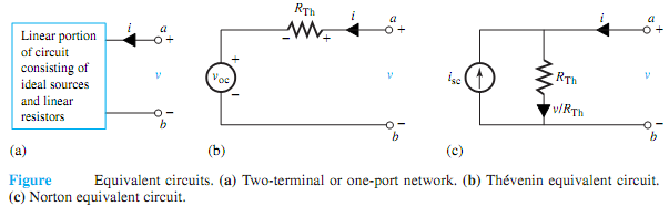
For a linear portion of a circuit consisting of ideal sources and linear resistors, the volt-ampere (v-i) relationship at any two accessible terminals can be expressed by the linear equation

v = Ai + B

where A and B are two constants. The Thévenin equivalent circuit at any two terminals a and b (to replace the linear portion of the circuit) is given by

v = RThi + voc

where it can be seen that

RTh = v/i|voc = 0

and

voc = v|i=0

Thus, voc is known as the open-circuit voltage (or Thévenin voltage) with i = 0, and RTh is the Thévenin equivalent resistance (as seen from the terminals a-b) with voc = 0. Equation accounts for the ideal sources present in that linear portion of the circuit, as shown in Figure (a), where as Equation implies deactivating or zeroing all ideal sources (i.e., replacing voltage sources by short circuits and current sources by open circuits). Themodel with the voltage source voc in series with RTh is known as Thévenin equivalent circuit, as shown in Figure(b).

Equation may be rewritten as

i = v / A - B / A = v / RTh - voc / RTh = v / RTh - isc

which is represented by the Norton equivalent circuit with a current source isc in parallel with RTh, as shown in Figure. Notice that with v = 0, i = -isc. Also, isc = voc/RTh,or voc = iscRTh.

1763_Thevenin equivalent circuit.png


Related Discussions:- Explain thevenin and norton equivalent circuits

Find the current source, Q. Consider the circuit shown in Figure. (a) Gi...

Q. Consider the circuit shown in Figure. (a) Given v(t) = 10e -t V, find the current source is(t) needed. (b) Given i(t) = 10e -t A, find the voltage source v (t) needed.

Explain working of voltmeter, Q. Explain working of Voltmeter? In order...

Q. Explain working of Voltmeter? In order tomeasure the potential difference between two terminals or nodes of a circuit, a voltmeter is connected across these two points. A pr

What are the functional types used in control words of 8251a, What are the ...

What are the functional types used in control words of 8251a? The control words of 8251A are divided into two functional types. 1. Mode Instruction control word 2. Comman

What do you understand by orthographic projection, What do you understand b...

What do you understand by orthographic projection ? Illustrate with the help of Matrix representation.

Determine the fault current and the bus voltages, The one line diagram of a...

The one line diagram of a simple three-bus power system is shown in the figure below.  Each generator is represented by an emf behind the transient reactance.  All impedances are e

Model and simulaions, a short review article on the classification of time ...

a short review article on the classification of time frame

What insulators have in large size, Insulators have (A) A full valence...

Insulators have (A) A full valence band. (B) An empty conduction band. (C) A large energy gap. (D)All the above. Ans: Insulators have a large energy gap.

\, Refer to Figure 100. Assume MKS units. Given: R1= 4, R2=14, R3= 9, I4...

Refer to Figure 100. Assume MKS units. Given: R1= 4, R2=14, R3= 9, I4= 8, I5= 7. Determine: Ieq, Req, and V3.

Transmission and swiching systems, using a combination of uniselectors and ...

using a combination of uniselectors and two motion selectors, draw a schematic of thousand line exchange and explain its working

Write Your Message!

Captcha
Free Assignment Quote

Assured A++ Grade

Get guaranteed satisfaction & time on delivery in every assignment order you paid with us! We ensure premium quality solution document along with free turntin report!

All rights reserved! Copyrights ©2019-2020 ExpertsMind IT Educational Pvt Ltd