Explain about interrupt-processing sequence, Computer Engineering

Assignment Help:

Q. Explain about Interrupt-Processing Sequence?

The occurrence of an interrupt fires a numbers of events both in processor hardware and software. Figure below displays a sequence.

1305_Explain about Interrupt-Processing Sequence.png

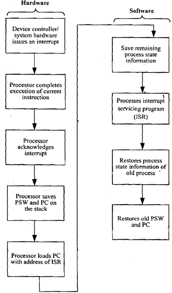
Figure: Interrupt-Processing Sequence

When an I/O device completes an I/O operation, the below sequence of hardware events takes place: 

1. The device issues an interrupt signal to processor.

2. Processor completes execution of current instruction before responding to interrupt.

3. Processor tests for interrupts and sends an acknowledgement signal to device that issued the interrupt.

4. The minimum information needed to be stored for task being currently executed before CPU starts executing interrupt routine (using its registers) are: 

(a) Status of processor that is contained in register known as program status word (PSW), and

(b) Location of next instruction to be executed, of currently executing program that is contained in program counter (PC).

5. Processor now loads PC with entry location of interrupt-handling program which will respond to this interrupting condition. Once PC has been loaded, processor proceeds to execute next instruction, which is the next instruction cycle that begins with an instruction fetch. Since the instruction fetch is determined by contents of the PC, result is that control is transferred to interrupt-handler program. The execution results in the subsequent operations:

6. PC & PSW relating to interrupted program have already been saved on system stack. Additionally the contents of processor registers are also needed to be saved on stack which are used by called Interrupt Servicing Routine since these registers may be modified by interrupt-handler. Figure (a) displays a simple illustration. Here a user program is interrupted after instruction at location N. Contents of all of registers and address of next instruction (N+1) are pushed on to stack.

7. Interrupt handler next processes interrupt. This involves determining of event which caused the interrupt and also status information relating to I/O operation.

8. When interrupt processing is finish, saved register values are retrieved from stack and restored to registers that are displayed in Figure (b).

9. Final step is to restore values of PSW and PC from stack. Consequently the instruction to be executed will be from previously interrupted program.


Related Discussions:- Explain about interrupt-processing sequence

Components of flash, A piece of art can be looked at as having 3 main compo...

A piece of art can be looked at as having 3 main components, the subject, the composition and the content. Subject The subject of an artwork is, in simple terms, the object

Storage devices, Logic manufactures have produced 'large scale' logic (LSI)...

Logic manufactures have produced 'large scale' logic (LSI) blocks to achieve complex functions; a typical set of logic functions is that of data storage. There are two main types o

Number of addresses in an instruction, Generally the Instruction Set Archit...

Generally the Instruction Set Architecture (ISA) of a processor can be distinguished using five categories:  Operand Storage in the CPU - Where are the operands kept other t

What is a manifest, What is a Manifest?  An assembly manifest contains...

What is a Manifest?  An assembly manifest contains all the metadata required to specify the assembly's version requirements and security identity, and all metadata required to

Discuss the basic entities of world wide web in brief, Discuss the basic en...

Discuss the basic entities of World Wide Web in brief. World Wide Web: This is a complicated client/server system in that a web client communicates along with the web ser

Illustrate the state diagrams of dynamic modelling, Dynamic modelling: stat...

Dynamic modelling: state diagrams A state diagrams allow you to further explore operations and attributes which need to be defined for an object. They comprises of sets of sta

Explain the input stage of an ADC, Explain the Input Stage of an ADC. ...

Explain the Input Stage of an ADC. Ans. Input Stage- In ADC at the input stage, analog voltage can contain any value in a range although the digital output can contain

Explain working of bit serial associative processor, Q. Explain working of ...

Q. Explain working of Bit Serial Associative Processor? When associative processor accepts bit serial memory organization subsequently it is known as bit serial associative pr

How to clear a datagrid on a button click, How to clear a datagrid on a but...

How to clear a datagrid on a button click? You require to Clear the DataSource of the dataGrid. So try this: dataSet1.Clear(); dataGrid1.DataSource = dataSet1.TableNam

Digital communication systems, a pcm has the following parameters a maximum...

a pcm has the following parameters a maximum analog input frequency of 4khz maximum decoded voltage at the receiver of 2.55v minimum dr of 6db compute minimum sampling rate,minimum

Write Your Message!

Captcha
Free Assignment Quote

Assured A++ Grade

Get guaranteed satisfaction & time on delivery in every assignment order you paid with us! We ensure premium quality solution document along with free turntin report!

All rights reserved! Copyrights ©2019-2020 ExpertsMind IT Educational Pvt Ltd