Evaluate bending moment for overhanging beam, Mechanical Engineering

Assignment Help:

Evaluate Bending moment for overhanging beam:

Draw the shear force & bending moment diagrams for 15 m span overhanging beam, that overhangs on both sides. This is subjected to a u.d.l. of 5 kN/m on left side overhanging portion of length 5 m and a u.d.l. of 4 kN/m on right side overhanging portion of length 4 m. Mention the numerical values at all of salient points.

Solution

To determine Reaction at B

letting right side, the moments around A,

MA       =+ R B × 6 - 4 × 4 × ( 6 + (4/2))

MA = 6 RB - 128

Letting left side, take moments around A,

M A = ( 5 × 5 × (5/2))  = - 62.5

Equating these two values, we obtain

6 RB - 128 = - 62.5

6 RB = 65.5

RB = 10.92 kN

RA =  (5 × 5) + (4 × 4) - RB

RA = 41 - 10.92 = 30.08 kN

Shear Force (Starting from the left end C)

 SF at C, FC = 0

SF just left of A, FA = 0 - 5 × 5 = - 25 kN

SF just right of A, FA = - 25 + 30.08 = + 5.08 kN

SF just left of B, FB = + 5.08 kN

SF just right of B, FB = + 5.08 + 10.92 = + 16 kN

SF at D, FD = + 16 -  (4 × 4) = 0
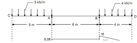
1494_Evaluate Bending moment for overhanging beam.png

Figure

Bending Moment

BM at C and D, MC  = MD = 0

BM at A, MA = - 5 × 5 ×(5/2) = - 62.5 kN m

BM at B, MB = - 4 × 4 ×(4/2) = - 32 kN m


Related Discussions:- Evaluate bending moment for overhanging beam

Ignition system-electrical system , Ignition System: The ignition system i...

Ignition System: The ignition system is a source and a means of initial spark required to start burning of fuel. A very high voltage supplied at the spark plug tip causes this spa

Determine the initial radius of curvature, Determine the initial radius of ...

Determine the initial radius of curvature:  A carriage spring, defiantly loaded and simply supported at its ends, has 12 steel plates each 60 mm wide by 6 mm thick. If the lon

Tolerances, difference between geometric and amnufacturing tolerances

difference between geometric and amnufacturing tolerances

Engfine, how we made parts of engine

how we made parts of engine

Draw the gas welding system, Draw the Gas welding System and label its part...

Draw the Gas welding System and label its parts. Illustrate the several types of flames used in gas welding along with temperature range.

Steam turbine, Stea m Turbine: INTRODUCTIO N:   Steam turbine is ch...

Stea m Turbine: INTRODUCTIO N:   Steam turbine is chief mover in which rotary motion can be obtained by a gradual change of momentum of steam. The force exerted on blade is

Welding, pre heating of casted material for welding

pre heating of casted material for welding

Illustrate the general shear failure in bearing capacity, Illustrate the ge...

Illustrate the general shear failure in bearing capacity. General Shear Failure: In this case of failure, contiguous failure surfaces develop between the edges of the footin

Write Your Message!

Captcha
Free Assignment Quote

Assured A++ Grade

Get guaranteed satisfaction & time on delivery in every assignment order you paid with us! We ensure premium quality solution document along with free turntin report!

All rights reserved! Copyrights ©2019-2020 ExpertsMind IT Educational Pvt Ltd