Dielectric heating - stepper motor , Electrical Engineering

Assignment Help:

Dielectric Heating

Dielectric  losses  occur in  insulating materials. These are same  as hysteresis losses  in magnetic materials. When  an alternating  electric  field  is applied to an insulating materials due to inter atomic  friction the atoms  get stressed and  heat is produced. This inter atomic friction caused by repeated deformation and rotation of  atomic  structure constituting the dielectric due to which  dielectric  loss occurs.

An atom of any  materials  has  a nucleus with a net positive charge at the  centre and negatively charged electrons surrounding the nucleus. Shown that when  there is no electric field the centred of positive and negative charge  are coincided. As the electric field  is applied to the atom the positive  charge of the  nucleus is forced in the  direction of field  and the negative charge  is forced  in the opposite direction of field  as shown in figure .

399_Dielectric Heating.PNG

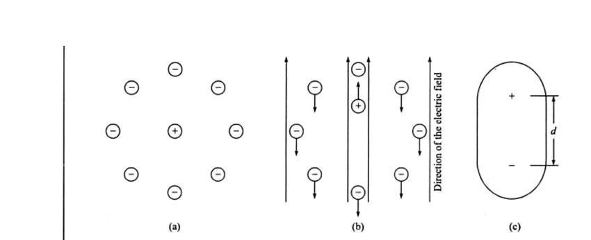
                 figure  (a) An atom without  electric field(b) an atom  with electric field and (c)  equivalent  of

Let  the two  centres are displaced by a distance d as shown  in figure. This gives  rise to  the electric dipole moment of magnitude P= qd. This state is known  as polarization. With increase in electric field strength the degree of polarization is increased. At a certain value  of electric fields  all  electric  dipoles align themselves. In this condition the dielectric material is said to be saturated. This state  is shown in figure .

2446_delectric  heating 2.PNG

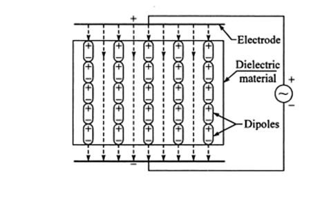
                                                                      Figure  Alignment  of electric dipoles

In dielectric  heating it is desirable to use high  frequency instead of high  voltage. If very  strong  electric field  is applied to insulating material then it  may possible.

That the strong  electric  fields may brings  out electron form  the orbit  resulting in a rupture of the dielectric  medium. Therefore  the applied  voltage  should always below  the breakdown  values.

The  principle  of operation of  dielectric heating can be explained by  an example. Consider  a piece of insulator. When an alternating voltage  is applied across this an  electric current  flows. Which may have two component  capacitive  current  and resistive current.  Obviously  leads applied voltage  by 900 and iR will be phase with  v as shown in figure.

504_Dielectric Heating.PNG 23.PNG

                       Figure (a) Dielectric  heating of a insulating material (b) equivalent circuit (c) phase or diagram

It behaves like a  insulating  resistance  parallel to capacitor as shown  in figure  the dielectric  loss  appears in the form  of heat  in the  dielectric of the capacitor.


Related Discussions:- Dielectric heating - stepper motor

Hlt halt instruction , HLT Halt Instruction The microprocessor halts  ...

HLT Halt Instruction The microprocessor halts  the execution  of the  program and enters into  the wait  state  the address  and data bus are placed in the  high  impedance st

Eletronic circuits, compensation techniques and biasing arrangements of q-p...

compensation techniques and biasing arrangements of q-point

Minimized circuit not -or and gate, 1.  Given S(D1) = !Q1 X + !Q1 Q0 + Q1 !...

1.  Given S(D1) = !Q1 X + !Q1 Q0 + Q1 !Q0 !X                                                        and       S(D0) = !Q1 !Q0 !X + Q0 X + Q1 !Q0 !X       A.  DRAW A MINIMI

Antenna fundamentals, Antenna Fundamentals We shall discuss here only t...

Antenna Fundamentals We shall discuss here only the fundamental concepts needed to understand the role of an antenna as a power-coupling element of a system. Figure illustrates

Explain the power chart, Explain the Power Chart The phasor diagram sho...

Explain the Power Chart The phasor diagram shown in Figure with the x and y axes added, as shown. This diagram may be converted to a 'power chart' by multiplying each phasor in

Inductive coupling, #question. i want design of inductive coupling to trans...

#question. i want design of inductive coupling to transfer power @ 2 watt in air gap of 5mm radial distance..

Explain ferrites suitability for high frequency application, Explain Suitab...

Explain Suitability of ferrites for high frequency application. Ferrites are extensively used in micro wave equipments and in computers. Ferrites are advantageous at high frequ

Find the voltage, Q. The current sources in Figure are given to be I A = 3...

Q. The current sources in Figure are given to be I A = 30 A and I B = 50 A. For the values of R 1 = 20 ,R2 = 40 , and R3 = 80 , find: (a) The voltage V. (b) The current

Electric Optic Device, Transmission Through a LiNb0 3 Plate Examine the tr...

Transmission Through a LiNb0 3 Plate Examine the transmission of an unpolarized He-Ne laser beam (?o= 633 nm) normally incident on a LiNb0 3 plate (ne = 2.29, no = 2.20) of thickn

Cro, Diagram and explanation of cro

Diagram and explanation of cro

Write Your Message!

Captcha
Free Assignment Quote

Assured A++ Grade

Get guaranteed satisfaction & time on delivery in every assignment order you paid with us! We ensure premium quality solution document along with free turntin report!

All rights reserved! Copyrights ©2019-2020 ExpertsMind IT Educational Pvt Ltd