Determine the value of maximum bending moment, Mechanical Engineering

Assignment Help:

Determine the value of maximum bending moment:

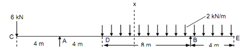
Draw the shear force & bending moment diagrams for the beam overhanging on both of sides as illustrated in Figure. Determine the magnitude of maximum positive and maximum negative bending moment and also situate the point of contraflexure, if any exist.

Solution

Letting right side, take moments around A,

MA = RB × 12 - 2 × 12 × 10

MA = 12 RB - 240

Considering left side, take moments about A,

MA = - 6 × 4 = - 24 kN m

Equating these two values, we get the reaction at the support B,

12 RB - 240 = - 24

RB = 18 kN

RA = 6 + (2 × 12) - RB = 30 - 18 = 12 kN

Shear Force (Starting from the left end C)

SF at C, FC = - 6 kN

SF just left of A, FA = - 66 kN

SF just right of A, FA = - 6 + 12 = + 6 kN

SF at D, FD = + 6 kN

SF just left of B, FB = + 6 - (2 × 8) = - 10 kN

SF just right of B, FB = - 10 + 18 = + 8 kN

SF at E, FE = + 8 - (2 × 4) = 0.

1357_Determine the value of maximum bending moment.png

Figure

BM at C and E, MC  = ME = 0

BM at B, MB = - ( 2 × 4 × (4/2) )  = - 16 kN m

BM at D, MD =+ (18 × 8) - ( 2 × 12 × (12/2)  = 0

BM at A, MA = - (6 × 4)  = - 24 kN m

Maximum Bending Moment

Let a section XX at a distance 'x' from the end E. SF at section XX,

Fx = - 18 + 2x

For maximum bending moment, Fx must be zero.

- 18 + 2x = 0

∴          x = 9 m

BM at any section XX among D and B,

Mx = 18 (x - 4) - 2x ×(x/2)

= 18 (x - 4) - x2

Mmax = 18 (9 - 4) - 92  = 9 kN m

Maximum negative bending moment = -24 kN m

Maximum positive bending moment = + 9 kN m


Points of Contraflexure

Assume M and D is the points of contraflexure where the BM changes sign.

To determine the position of M, equate the moment equation among D and B to zero.      

                        18 (x - 4) - x2 = 0

                        - x2 + 18x - 72 = 0

or,                     x2 - 18x + 72 = 0

We obtain,       x = 6 m and x = 9 m.

There are two points of contraflexure, one of at a distance of 6 m & the other at a distance of 9 m from the end E.


Related Discussions:- Determine the value of maximum bending moment

Hartnell Governor, How we could build the working model of hartnell governo...

How we could build the working model of hartnell governor?

Determine the maximum permissible eccentricity of the load, Determine the m...

Determine the maximum permissible eccentricity of the load: A small hollow cylindrical column carries a compressive force of 400 kN. The external diameter of the column is 200

Determine the time response for the system, For two waves period, determine...

For two waves period, determine the time response x(t) for the system (ignoring viscous damping effect only)  Give=n: X0=0.09615 , θ(radians)=0.110*π , μk=0.80000 , μs=0.90000 , K=

Dynamics, a motorcycle is used to stunt show to go over a valley . if the i...

a motorcycle is used to stunt show to go over a valley . if the initial speed at A is u m/s, determine a. the minimum U so that the motorcycle reaches the bank at B. b. the veloc

Why we use nickel alloys in welding, Q. Why we use Nickel Alloys in welding...

Q. Why we use Nickel Alloys in welding? Nickel weld metals have high creep-rupture strength but often have lower stress-rupture ductility and lower mechanical and thermal fatig

List out the types of fixtures, List out the Types of fixtures? Mil...

List out the Types of fixtures? Milling fixtures Lathe fixtures. Grinding fixtures Broaching fixtures Assembly fixtures Inspection fixtures Boring f

Cutting test, Cutting Test:             Once the sand blasted blade we...

Cutting Test:             Once the sand blasted blade were went through the washing process. Quality Control technician will randomly pick 15 pieces of blade to go for cutting

Shielding gas-argon - hydrogen mixtures, Argon - Hydrogen Mixtures A...

Argon - Hydrogen Mixtures Argon - hydrogen mixtures are employed in special cases, such as mechanised welding of light gauge stainless steel tubing, in which the hydrogen do

Indicator diagram and indicated power - thermodynamics, Indicator diagram a...

Indicator diagram and indicated power: An indicated diagram is graph between pressure and volume. The former being taken on the vertical axis and latter on the horizontal axis

Boilers, BOILERS: BOILERS : Boilers can be defined as closed pressu...

BOILERS: BOILERS : Boilers can be defined as closed pressure vessels that are used to generate steam at pressure much higher than atmospheric pressure by the transfer of he

Write Your Message!

Captcha
Free Assignment Quote

Assured A++ Grade

Get guaranteed satisfaction & time on delivery in every assignment order you paid with us! We ensure premium quality solution document along with free turntin report!

All rights reserved! Copyrights ©2019-2020 ExpertsMind IT Educational Pvt Ltd