Determine the time delay of the cable, Electrical Engineering

Assignment Help:

Q. Determine the time delay of the cable?

An RG-213/U (radio guide 213/universal coaxial cable) is a small-sized, flexible, double-braided cable with silvered-copper conductors, and a characteristic impedance of 50 . The characteristic impedance ¯Z0(= R0) is related to the cable's geometrical parameters by

1412_Determine the time delay of the cable.png

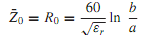
where εr is the relative permittivity (dielectric constant) of the dielectric, and b and a are the radii of the outer and inner conductors, respectively. The velocity of wave propagation in a coaxial line is vg = c/√εr , where c = 3 × 10⁸ m/s is the velocity of light. The cutoff frequency, given by

366_Determine the time delay of the cable1.png

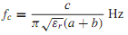
puts an upper bound for wave propagation. The attenuation due to conductor losses is approximately given by

1070_Determine the time delay of the cable2.png

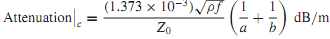
where ρ is the resistivity of the conductors. Attenuation due to dielectric losses is given by

316_Determine the time delay of the cable3.png

where tan is known as the loss tangent of the dielectric.

wth a = 0.445 mm, b = 1.473 mm, εr = 2.26 for polyethylene dielectric, tan δ = 2×10⁻⁴, and ρ = 1.63×10⁻⁸m, calculate the total line attenuation at 100 MHz, and check the value of ¯Z0(= R0) in the specification. If the cable connects an antenna to a receiver 30 m away, determine the time delay of the cable, the velocity of wave propagation, and the cutoff frequency.


Related Discussions:- Determine the time delay of the cable

Write short note on common vs associated channel signalling, Q. Write short...

Q. Write short note on Common vs. associated channel signalling. Associated vs. Common channel signalling: Out band signalling suffers from very limited bandwidth. Both a

Cro, role of trigger circuit in cro

role of trigger circuit in cro

Step up chopper - power supplies , Step Up Chopper In this  chopper av...

Step Up Chopper In this  chopper average output  voltage  is greater than  input  voltage. The circuit  different  mode  of operation and  current  waveforms are show. When

Obtain the value of rs, Consider and obtain the values for R S , R 2 , R 1 ...

Consider and obtain the values for R S , R 2 , R 1 , and R D . Apply the rule-of-thumb dc design procedure outlined in this section for a JFET with V P = 3V, I DSS = 20 mA, and a

Define memory for a digital computer, Q. Define Memory For a digital comput...

Q. Define Memory For a digital computer? For a digital computer which stores both programs and data, memory can be divided into three types: random-access memory, mass storage,

Why two rectifier is used in smps, Its not essential that a power plant use...

Its not essential that a power plant uses only two rectifiers, it depends on the load there at the site and the capacity of the rectifier or SMPS. Assume the load at the site is 12

Clipper, design a clipper circuit of a sinsoiudial wave of a peak value 25v...

design a clipper circuit of a sinsoiudial wave of a peak value 25v&minimum value of -12v to make the output voltages of 20&-9v respectively.

Name the modes used by the dma processor to transfer data, Name the three m...

Name the three modes used by the DMA processor to transfer data? The three modes are:- a) Signal transfer mode (cycling stealing mode) b) Block transfer mode c) Demand

How is segmentation implemented in typical microprocessors, How is segmenta...

How is segmentation implemented in typical microprocessors? The first advantage is as memory segmentation has is that only 16 bit registers are needed both to store segment bas

Write Your Message!

Captcha
Free Assignment Quote

Assured A++ Grade

Get guaranteed satisfaction & time on delivery in every assignment order you paid with us! We ensure premium quality solution document along with free turntin report!

All rights reserved! Copyrights ©2019-2020 ExpertsMind IT Educational Pvt Ltd