Determine ratio between mass flow rate to condensing steam, Mechanical Engineering

Assignment Help:

Determine ratio between mass flow rate to condensing steam:

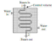
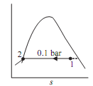
In steam power plant, the steam 0.1 bar and 0.95 dry enters condenser and leaves as saturated liquid at 0.1 bar and 45°C. Cooling water enters condenser in separate steam at 20°C and leaves at 35°C without any loss of its pressure and with no phase change. Neglecting heat interaction between condenser and surroundings and changes in kinetic energy and potential energy, determine ratio between mass flow rate of cooling water to condensing steam.              

Sol.: Given that:

Inlet condition of steam: Pressure 'P1' = 0.1 bar dryness fraction x = 0.95 The exit condition of steam saturated water at 0.1 bar and 45°C Inlet temperature of cooling water = 20°C Exit temperature of cooling water = 35°C Applying SFEE to control volume Q - Ws  = mf [(h2  - h1)+  ½(V22 - V12) + g(z2 - z1)]

1991_Determine ratio between mass flow rate to condensing steam.png

Figure

neglecting changes in kinetic and potential energies. And there is no shaft work that is.; Ws  = 0

Q = mf (h2  - h1)

h1 = hf1  + xhfg1

= 191.81 + 0.95 (2392.82) = 2464.99 kJ/kg

h2 = hf2  at 0. 1 bar (as the water is saturated liquid)

h2 = 191.81 kJ/kg

Q = mf (191.81 - 2464.99)

= - 2273.18mf  kJ/kg                              ...(i)

negative sign shows the heat rejection.


1973_Determine ratio between mass flow rate to condensing steam1.png

By energy balance; Heat lost by steam = Heat gained by cooling water

Q = mfw.Cw  (T4  - T3) = mfw  x 4.1868(35 - 20) = 62.802mf                ...(ii)

Equate equation (i) and (ii); We get Q = -2273.18mf  = 62.802mfwmfw/m = 36.19 Ratio of mass flow rate of cooling water to the condensing steam = mfw/mf  = 36.19                                                                      


Related Discussions:- Determine ratio between mass flow rate to condensing steam

Phycics, digram of michelson inteferometer

digram of michelson inteferometer

Draw bending moment diagram for the beam, Draw bending moment diagram for t...

Draw bending moment diagram for the beam: A cantilever beam carries a uniformly distributed load of 2 t/m over the total length of 6 m and point loads of 5 t, 3 t, 7 t & 2 t a

Calculate the greatest stress - plate, Calculate the greatest stress - plat...

Calculate the greatest stress - plate: A rectangular plate 10 mm thick within a hole of 50 mm diameter drilled on this is as shown in Figure 10. This is subjected to axial pul

Thermodynamics, define the first and second law of thermodynamics.

define the first and second law of thermodynamics.

Banking of a cyclist, what is the formula for measuring the safe speed to d...

what is the formula for measuring the safe speed to drive for a cyclist

What is the extension of auger, Extension of auger in the main auger arrang...

Extension of auger in the main auger arrangement The original size of screw conveyer without auger extension is 2.5 m., which is same as size of chassis. Which to be attach wit

Equation for principal stresses and principal planes, Equation for principa...

Equation for principal stresses and principal planes: Derive equation for principal stresses and principal planes for the element subjected to compound stresses. Sol.:

Calculate the moment of inertia , Calculate the centroid (use point A as th...

Calculate the centroid (use point A as the reference) and the moment of inertia of the shape shown in Figure. The dimensions are given in centimeters.  Calculate the moment

Write Your Message!

Captcha
Free Assignment Quote

Assured A++ Grade

Get guaranteed satisfaction & time on delivery in every assignment order you paid with us! We ensure premium quality solution document along with free turntin report!

All rights reserved! Copyrights ©2019-2020 ExpertsMind IT Educational Pvt Ltd