Determine forces in members of cantilever truss, Mechanical Engineering

Assignment Help:

Determine  forces in members of cantilever truss:

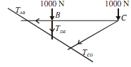
Determine  forces  in  members  BC  and  BD  of   cantilever truss  shown  in  the figure in the figure given below. 


329_Determine  forces in members of cantilever truss.png

Sol.: If we draw a section line that cut the member BC, BD, AD, ED, then the member BC and BD cut by this line, but this section line cut 4 members, so we do not use this section line. As a section line cut maximum of three members.

There is no single section line that cut the maximum 3 member and also cut member BC and BD.

This problem can be solved in following two steps.

(1)  Draw the section line which cut member BC and DC. Select any one section and find out value of BC.

(2)  Draw the new diagram, draw another section line that cut the member AB, BD and CD, and find out value of the member BD.

STEP-1

Draw the section line which cut member BC and CD, as shown in figure given below.


752_Determine  forces in members of cantilever truss1.png

Consider Right hand side of truss as shown in the figure given below

By taking moment about the point D

MD = 0

1000 x 2 - TBC  x BD = 0

Consider the ?CAE and CDB, they are similar

BD/AE = BC/AC BD/3 = 2/4

BD = 1.5m

1000 x 2 - TBC  x 1.5 = 0

TBC =   1333.33KN                                    ...(iii)

TBC = 1333.33KN (Tensile)                                    .......ANS

STEP-2:

Draw the section line that cut the member AB, AD and BD, as shown in figure given below.


1174_Determine  forces in members of cantilever truss2.png


Consider the Right hand side portion of truss as shown in the figure given below

By taking moment about the point C

MC  = 0

{Moment of force TAB, TCD  and 1000N acting at point C is zero}

-1000 x BD - TBD  x BC = 0

-1000 x 2 - TBD  x 2 = 0

265_Determine  forces in members of cantilever truss3.png

TBD  =  - 1000KN                                    ...(iii)

TBC  = 1000KN (compressive)         .......ANS


Related Discussions:- Determine forces in members of cantilever truss

Gyroscope, what is principle of gyroscope

what is principle of gyroscope

Changes in mechanical properties along with tempering, Changes in Mechanica...

Changes in Mechanical Properties along with Tempering: Tempering enhances the toughness and ductility of quenched steel though decreases hardness. Following figure demonstrate

What is wire-frame, What is Wire-frame Wire-frame models use the simpl...

What is Wire-frame Wire-frame models use the simplest data structures and they are ambiguous. Wire frame is a well-known example that consists of 16 vertices and 32 edges. We

Discover the increase in pressure, Discover the increase in pressure: ...

Discover the increase in pressure: A copper tube of 50 mm diameter and 1200 mm length contains a thickness of 1.2 mm along closed ends. This is filled with water at atmospheri

Expected service life of a component, Q. Expected service life of a compone...

Q. Expected service life of a component in high temperature environment? The expected service life of a component in a high temperature environment is limited by either the mat

Explain the creation phase of paver machine, Creation phase of Paver machin...

Creation phase of Paver machine: Objective: "To generate alternative methods for providing the function, through creative thinking, brainstorming and even speculation."

M.o.s, Draw the shear force and bending moment diagrams for overhanging bea...

Draw the shear force and bending moment diagrams for overhanging beam subjected to pont load at its free end

Explain the machining processes, Machining Processes In machining proce...

Machining Processes In machining processes, also known as Metal cutting or chip forming processes, material is removed from a work piece to get the final shape of the product.

Determine the relative error in the function, Determine the relative error ...

Determine the relative error in the function y = ax 1 m1 x 2 m2 ........x n mn If u = 4x 2 y 3 / Z 4 and error in x, y, z be 0.a, compute the relative maximum error in u ta

Compute minimum value of the horizontal force, Compute minimum value of the...

Compute minimum value of the horizontal force: Block A of weight 520N rest on horizontal top of block B having weight of 700N as shown in the figure given below. Block A

Write Your Message!

Captcha
Free Assignment Quote

Assured A++ Grade

Get guaranteed satisfaction & time on delivery in every assignment order you paid with us! We ensure premium quality solution document along with free turntin report!

All rights reserved! Copyrights ©2019-2020 ExpertsMind IT Educational Pvt Ltd