Deflection at the centre - simply supported beam, Mechanical Engineering

Assignment Help:

Deflection at the centre:

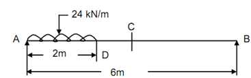
A simply supported beam of span 6 m is subjected to Udl of 24 kN/m for a length of 2 m from left support. Discover the deflection at the centre, maximum deflection & slopes at the ends and at the centre. Take EI = 20 × 106 N-m2.

Solution

∑ Fy  = 0, so that RA  + RB  = 24 × 2 = 48 kN          --------- (1)


2109_Deflection at the centre - simply supported beam.png

Taking moments around A,

24 × 2 × 1 = RB  × 6

RB  = 8 kN (↑)                     -------- (2)

RA  = 48 - 8 = 40 kN (↑).         ------------(3)

By apply the Udl over the portion DB downwards and upwards,


                                 Figure

M = 40 x - 24 x × (x/2) + 24 ( x - 2) ( (x - 2)/2)

Note down that the third term vanishes if x < 2 m.

= 40 x - 12 x2  + 12 ( x - 2)2               ------- (4)

EI d 2 y/ dx2 = 40 x - 12 x 2  + 12 ( x - 2)2          ------- (5)

EI dy / dx = 40 x2/2- 12 x3 /3+ 12 ( x - 2)3/3 + C1

= 20 x2 - 4 x3 + 4 ( x - 2)3 + C1           -------- (6)

EIy = 20 x 2/3 - x4 + (x - 2)4 + C1 x + C2            -------- (7)

Here again note that the third term vanishes for x < 2 m.

at A,      x = 0,    y = 0  ∴ C2  = 0

at B,  x = 6 m,     y = 0         

0 = 20 × 63 /3 - 64  + (6 - 2)4 + C1 × 6

C1 =- 20 × 12 + 36 × 6 - ((16 × 16 )/6)=- 200/3

∴          EI dy/dx = 20 x2  - 4 x3  + 4 ( x - 2)3  - 200/3         -------- (8)

The third term vanishes.

Slope at A, (x = 0),     27

θA  = -200/3EI =- (200 × 103)/ (3 × 20 ×106)

            = -(1/300) rad = - 3.33 × 10- 3  rad


Slope at B, (x = 6 m),

EI θ B = 200 × 62  - 4 × 63  + 4 (6 - 2)3  - (200/3)

 θ  = 136/ 3 EI = (136 × 103 )/(3 × 20 ×106)

= + 2.27 × 10- 3  radian

Slope at C, (x = 3 m), i.e. x > 2 m

EI θ C = 20 × 32  - 4 × 33  + 4 (3 - 2)3  - (200/3)

θC = 20 /3 EI = 0.47 × 10- 3  radians

EIy =( 20 x 3/3)- x4  + ( x - 2)4  - (200/3) x                   -------- (9)

Deflection at centre, (x = 3 m),

EIyC = (20/3) × 33  - 34  + (3 - 2)4  - (200 /3)× 3

yC  = - 100 / EI =  - 100 × 103 × 103 / (20 × 106)

= - 5 mm

For maximum deflection,

dy/ dx  = 0

0 = 20 x2  - 4x3  + 4 ( x - 2)3  - (200/3)

= 20 x2  - 4x3  + 4x3  - 32 - 24 x2  + 48 x - (200 /3)

=- 4x2  + 48 x - (296 /3)

∴          x2  - 12x + (74 /3 )= 0

x = 2.63 m , x > 2m

EIy max = (20/3) × 2.633  - 2.634  + (2.63 - 2)4  - (200/3) × 2.63 = - 101.7

∴ ymax  = - 5.087 mm;  - 5.1 mm


Related Discussions:- Deflection at the centre - simply supported beam

Engineering Mechanic, with usual notations the effort lost due to friction ...

with usual notations the effort lost due to friction is given by A) P-W/V.R B) P×V.R-W C) P-W×V.R D) P+W/V.R

Newton law of motion - third law, Newton law of motion - Thir d Law F...

Newton law of motion - Thir d Law Force of action and reaction between the bodies which are interacting are equal in magnitude, opposite in direction and have same line of ac

Ordinate dimensions-autocad, Ordinate Dimensions Ordinate dimensions ar...

Ordinate Dimensions Ordinate dimensions are not really a dimensions at all in that they did not indicate a measurement aur dimensions. Rather they annotate known co-ordinate po

Project, project on solid work 2012 The Final Project is to design a mechan...

project on solid work 2012 The Final Project is to design a mechanical assembly in Solidworks. The design must consist of a minimum of 60 parts, 30 of which must be unique. A uniqu

Define advantage and disadvantage of electron beam machining, Define Advant...

Define Advantage and Disadvantage of Electron Beam Machining Advantage  1. Suitable for automatic machining. 2. Absence of mechanical contact between work piece and too

Develop a computer-based methodology, Consider the U-shaped curved beam sho...

Consider the U-shaped curved beam shown below (with rectangular cross-section and thickness h ), which is loaded by force P as indicated. A free-body diagram reveals that a mome

Calculate the maximum bending moment, A shaft is supported on bearings A an...

A shaft is supported on bearings A and B, 800 mm between centres. A 20° straight tooth spur gear having 600 mm pitch diameter, is located 200 mm to the right of the left hand beari

Balancing, basics of static balancing.

basics of static balancing.

Explain objectives of radial drill machine, Explain Objectives of Radial dr...

Explain Objectives of Radial drill machine There are many objectives such like, 1.   With the help of angle drill machine, an angle hole can be produced at any angle.  2.

Write Your Message!

Captcha
Free Assignment Quote

Assured A++ Grade

Get guaranteed satisfaction & time on delivery in every assignment order you paid with us! We ensure premium quality solution document along with free turntin report!

All rights reserved! Copyrights ©2019-2020 ExpertsMind IT Educational Pvt Ltd